Archives: Stm32

callgrind profiling of embedded targets

When performing optimization or micro-optimization on desktop applications, callgrind combined with kcachegrind are one of my favorite combinations. While slow to run, it gives you precise information about where instructions are spent and has at least a decent way of moving up and down the call frame or digging into disassembly. The downside, is that it largely only works if you can run the application on your host processor, which isn’t that relevant when working with embedded targets like STM32 (or other) microcontrollers. Recently, I got fed up trying to find more cycles to shave off the moteus firmware, and decided to take a stab at making at least a minimal solution.

STM32G4 ADC performance part 2

Back last year, I walked through bisecting and debugging an annoying problem that caused the STM32G4 ADC on the moteus controller to exhibit higher than expected noise in result largely to either the exact placement in flash of the initialization code, or to the exact timing of the initialization. While the immediate glaring sharp edge was removed, the resulting performance still was confusing to me, and looked like it was not yet optimal. Further, a moderate percentage (2% or so), of production boards failed end-of-line tests related to the current sense noise in ways that were hard to fix by swapping components. Because of this, I wanted to dive in and investigate further. This is that process.

moteus external connector pin selection

moteus r4.11 has two external connectors, the ABS connector (AUX2) and the ENC/AUX1 connector. The ABS connector was designed initially just to have 2 I2C pins. The ENC connector just has the random pins that were used for the onboard encoder SPI plus one more. Thus the range of external accessories that can be connected is somewhat haphazard and not necessarily all that useful.

When working on a more ground up revision of the controller, I wanted to improve that situation to expose more connectivity options on still a relatively limited connector set. The idea was to use 2 connectors, one which has 5 I/O pins and the other with 4 I/O pins. The onboard encoder SPI would still be accessible on the larger connector to use for at least one external SPI encoder, but how much other functionality could be crammed into the remaining pins? To start, lets see what possible options there are in the current firmware and supported by the STM32G4 microcontroller that moteus uses:

Debugging bare-metal STM32 from the seventh level of hell

Here’s a not-so-brief story about troubleshooting a problem that was at times vexing, impossible, incredibly challenging, frustrating, and all around just a terrible time with the bare-metal STM32G4 firmware for the moteus brushless motor controller.

Background

First, some things for context:

moteus has a variety of testing done on every firmware release. There are unit tests that run with pieces of the firmware compiled to run in a host environment. There is a hardware-in-the-loop dynamometer test fixture that is used to run a separate battery of tests. There is also an end-of-line test fixture that is used to run tests on every board and some other firmware level performance tests.

Spurious writes to address 0x00000000 on an STM32

What happens if you accidentally write to address 0x00000000 on an STM32 microcontroller? Answer: usually almost nothing, because most linker scripts by default map a bank of flash there, and you can’t write to flash normally. The flash controller does notice and sets an error flag, but most applications aren’t exactly checking the flash peripheral’s error flags on a regular basis.

However, if you use the HAL to try and perform a flash operation, it doesn’t bother checking the error flags *before* trying to perform an operation. It just tries, and reports any errors it observes at the end. So, if you have an application that occasionally makes a spurious write to the zero address, and also performs flash operations, it will manifest as spurious failures of the flash operations.

Spread spectrum integration

I’ve been developing a new bi-directional spread spectrum radio to command and control the mjbots quad robot.  Here I’ll describe my first integration of the protocol into the robot.

To complete that integration, I took the library I had designed for the nrfusb, and ported it to run on the auxiliary controller of the pi3 hat.  This controller also controls the IMU and an auxiliary CAN-FD bus.  It is connected to one of the SPI buses on the raspberry pi.  Here, it was just a matter of exposing an appropriate SPI protocol that would allow the raspberry pi to receive and transmit packets.

Spread spectrum implementation

With a protocol design in hand, the next step was to go and implement it.  My goal was to produce a library which would work on the nrfusb, and also on the auxiliary stm32g4 on the mjbots pi3 hat.  In this first implementation pass however, I only worked with the nrfusb as both transmitter and receiver.

While developing this, I had more than my share of “huh” moments working from the datasheet and with the components.  To begin with, the initial nrf24l01+ modules I got were all Chinese clone ones.  While I was having problems getting auto acknowledgement to work, I discovered that the clones at a minimum were not compatible with genuine Nordic devices.  Thus I reworked genuine parts into the modules I had:

Power distribution board r3

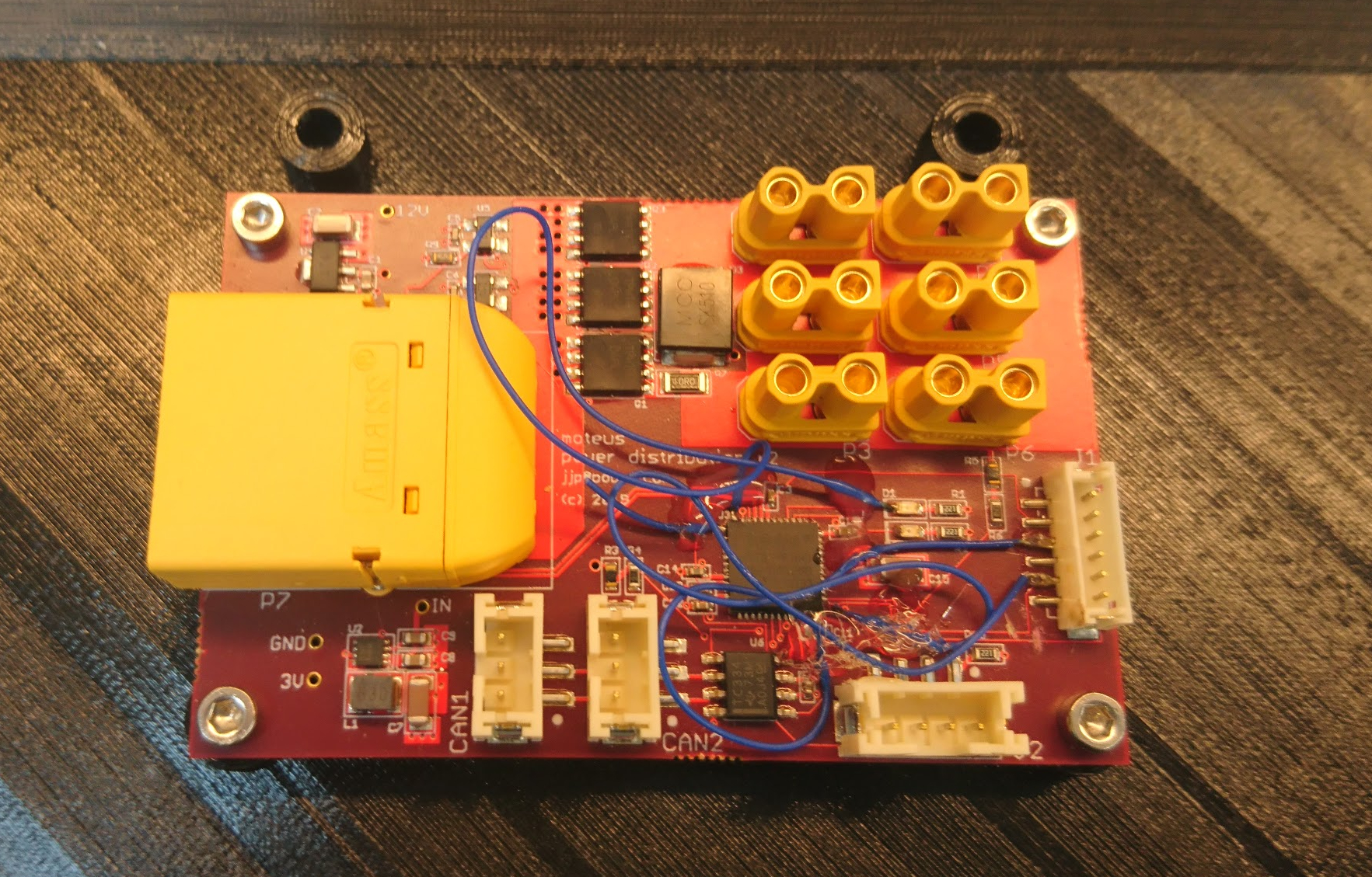
While I was able to make the r2 power distribution board work, it did require quite a bit more than my usual number of blue wires and careful trace cutting.

dsc_0394

Thus I spun a new revision r3, basically just to fix all the blue wires so that I could have some spares without having to worry about the robustness of my hot glue.  While I was at it, I updated the logo:

Bringing up CAN on the quad pi3 hat

After getting the power to work, the next step in bringing up the new quad’s raspberry pi interface board is getting the FDCAN ports to work.  As described in my last roadmap, this board has multiple independent FDCAN buses.  There are 2 STM32G4’s each with 2 FDCAN buses so that every leg gets a separate bus.  There is a 5th auxiliary bus for any other peripherals driven from a third STM32G4.  All 3 of the STM32G4’s communicate with the raspberry pi as SPI slaves.

Bringing up the IMU on the pi3 hat

The next peripheral to get working on the quad’s raspberry pi interface board is the IMU. When operating, the IMU will primarily be used to determine attitude and angular pitch and roll rates.  Secondarily, it will determine yaw rate, although there is no provision within the IMU to determine absolute yaw.

To accomplish this, the board has a BMI088 6 axis accelerometer and gyroscope attached via SPI to the auxiliary STM32G4 along with discrete connections for interrupts.  This chip has 16 bit resolution for both sensors, decent claimed noise characteristics, and supposedly the ability to better reject high frequency vibrations as seen in robotic applications.  I am currently running the gyroscope at 1kHz, and the accelerometer at 800Hz.  The IMU is driven off the gyroscope, with the accelerometer sampled whenever the gyroscope has new data available.