Archives: 2019

Endurance testing moteus controller r4.1

Before ordering a bigger batch of the new moteus r4.1 controller, I wanted some assurance that it would be able to run for an extended periods of time under representative loads while not breaking or having thermal issues.
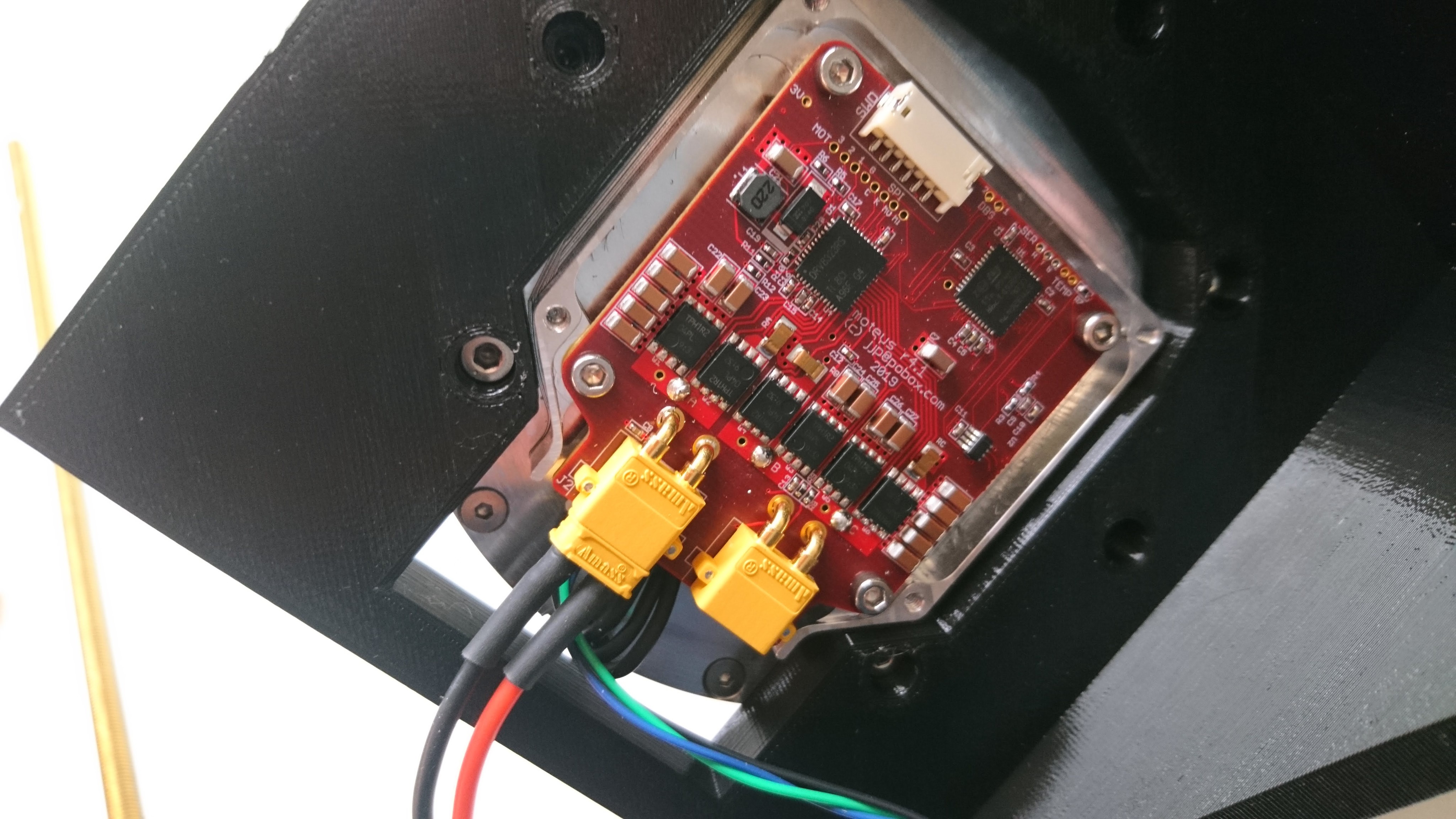
r4.1 mounted up

r4.1 mounted up

When I did this for the r3.1 controller, I had 2 motor joints and a planar leg built and did a jumping endurance test.  I could have done that now, but building up a leg fixture was more work than I wanted to mess with at the moment, so I went with a simpler approach:

My first non-Fusion generated g-code

While working to build a weight reduced moteus servo mk2, I reworked my outer housing CAM to do all the machining on the Pocket NC v2-50.  For this part I didn’t necessarily need any challenging workholding and since I could get the stock in tube form, there wasn’t an inordinate amount of material to remove either.

The one challenge is that when mounted in the Sherline Chuck, the mill can’t actually reach all the way to the edge of the part without hitting the X travel limit (which is why most of the other 100mm diameter parts I do are fixtured slightly off-center).  In this case I tackled the problem in two iterations.

Bringing up the fdcanusb

I introduced the fdcanusb previously, now I’ll describe some of the process and challenges in getting it to work.

Hardware

My initial challenges were around the PCB design and manufacturing.  To begin with, my very first revision was sent out for manufacturing with the same incorrect pinout as the moteus controller r4.0 and thus was only really usable as a paperweight.  Second, the supply of STM32G474 chips seems to be spotty now, so for r2 I had to scavenge chips from the boards that had broken pinouts.

fdcanusb

One of the necessary pieces for bringing up the moteus brushless controller and for ongoing development with it is being able to communicate with the device on the desk.  There aren’t many options for desktop FDCAN communication currently, and certainly none that are in the affordable range occupied by the [CANUSB family of devices](http://CANUSB family of devices) which I’ve used before and was very happy with.  Thus I created “fdcanusb”, a USB to FDCAN converter that allows one to communicate with FDCAN devices via a USB interface using a documented protocol, no drivers necessary.

More adventures in STM32G4 bringup

Last time I had an actually hard problem…, a mis-aligned stack which caused randomly misbehaving software.  This time, I had a more prosaic problem.  One that while not necessarily as interesting, was even more time consuming and frustrating.

The serial port wouldn’t work.  I had copied the module I used for DMA based receive and transmit from the STM32F4 and it just wasn’t working.  Nothing was written and nothing was received.  I carefully inspected the software many times.  I looked at the registers in the debugger and nothing seemed obviously amiss.  I read the datasheet to look for subtle differences in the theory of operation between the STM32F4 and STM32G4 but came up empty.

moteus servo mk2: Reducing weight

After having produced the first functional demonstration of the moteus servo mk2, my next step was to decrease the weight.  While I was at it, I made two other changes:

  • Axial connections: I switched to a design with entirely axial connectors, which removes the need for 4th axis machining when producing the parts.
  • Planet Input Bearing: I switched the planet input bearing to be inserted from the rotor side.  This way, the bearing is captured between the planet input and the rotor, rather than between the planet input and the gears.  That also improves the ability to assemble and disassemble the unit.

moteus_mk2_reduced_weight_2

moteus controller r4.1

Another step in my plan for the next revision of the moteus servo mk2, is an updated controller board.  As mentioned in my roadmap, I wanted to revise this board to make improvements in a number of domains:

  • Communications: Now instead of RS485, the primary communications interface is FD-CAN.  This supports data rates of up to 8 Mbit and packet lengths up to 64 bytes.  The header is nominally at the original CAN bit rate, but I have no need to be standards compliant and am running very short busses so I may run everything at the higher rate.
  • Connectors: Now there exist power connectors, in the form of XT30 right angle connectors and they are also daisy chainable like the data connectors.  Additionally, all the connectors exit from the bottom of the board to make routing easier in configurations like the full rotation leg.
  • Controller: This uses the relatively new STM32G4 controller series.  It is lower power than the STM32F4, supports FD-CAN, and also supports closely coupled memory, which may allow me to improve the speed of the primary control loop execution by 3 times.
  • Voltage range: This board now has 40V main FETS, with all other components at 50V rating or higher.  Thus it should be safe with inputs up to 8S (34V or so).
moteus r4.1 rendering

moteus r4.1 rendering

Update on Pocket NC v2-50 Threadmilling

After machining a fair number of parts with threads, I’ve tweaked my thread milling feeds and speeds to both go a little bit faster, give a more reasonable fit, and remove the last bit of niggling interference with the M2.5 recipe.

I’ll list the changes here, and have updated the original recipe

Old New
Chamfer Width 0.10mm 0.05mm
M3 Pitch Diameter Offset 0.538mm 0.568mm
M3 Stepovers 10 6
M3 Repeat Passes NO YES
M3 Lead To Center NO YES
M2.5 Pitch Diameter Offset 0.430mm 0.480mm
M2.5 Stock to Leave 0.0mm -0.02mm
M2.5 Stepovers 7 4
M2.5 Repeat Passes NO YES
M2.5 Lead To Center NO YES

Notably, the “Lead To Center” option found on the linking tab is what prevents the M2.5 threads from rubbing when inserting in later passes.  Thanks to Quincy Jones from Implemented Robotics for that tip over in the mjbots discord!