Archives: 2022

Debugging bare-metal STM32 from the seventh level of hell

Here’s a not-so-brief story about troubleshooting a problem that was at times vexing, impossible, incredibly challenging, frustrating, and all around just a terrible time with the bare-metal STM32G4 firmware for the moteus brushless motor controller.

Background

First, some things for context:

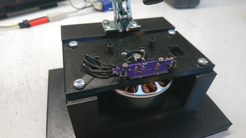
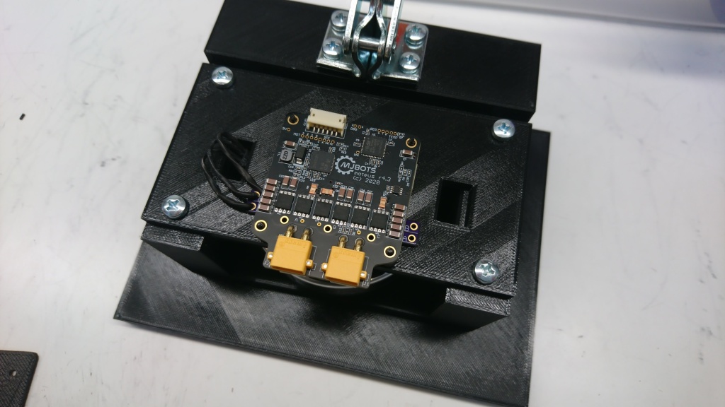
moteus has a variety of testing done on every firmware release. There are unit tests that run with pieces of the firmware compiled to run in a host environment. There is a hardware-in-the-loop dynamometer test fixture that is used to run a separate battery of tests. There is also an end-of-line test fixture that is used to run tests on every board and some other firmware level performance tests.

Updated moteus test fixture

I documented the first test fixture I built for moteus some time ago. As the shipment volumes have gone up, the fixture became something of a limitation, and also was a little problematic in a few ways.

The old “state of the art”

First, it relied on attaching 3 connectors by hand for each test, which was a decent fraction of the cycle time. Second, the pogo pins it used were non-replaceable, and also connected only to the debug phase wire test vias, which were tiny. They wore out relatively quickly, and replacing them required building a whole new board. Finally, since the pogo pins were PCB mounted, a PCB needed to be printed for any change in the pin locations or which pins to probe.

moteus firmware release 2022-07-11

It has been on github for a few days now, but I’m excited to announce the newest moteus firmware release, 2022-07-11. This release includes some big features, and some quality of life improvements all around.

  • Flexible I/O subsystem: This release includes the new flexible I/O subsystem. This adds support for many new encoder types and lets you connect them up in a wide variety of ways.
  • Cogging torque compensation: Preliminary support for cogging torque compensation is present in this release. It works pretty well on a number of motor types already, future articles will describe it in more detail.
  • Encoder eccentricity compensation: This feature lets you linearize the output position and velocity in the face of non-linear encoder readings. A write-up for it is also forthcoming in the not-too-distant-future.
  • Transparent no-BRS CAN-FD communication: If your CAN-FD network is only capable of operating at 1Mbps, and you send queries frames with BRS turned off, moteus will now respond in kind. This eliminates most needs to change the CAN bus frequency due to marginal electrical properties.

This is an exciting time for moteus, and the new features will keep coming!

Flexible I/O: Sink configuration

This will be the final post describing the fundamentals of configuring the new flexible I/O system. There have been a number of previous posts (part 1, part 2, part 3). In this iteration, we’ll cover how to configure the sinks that consume the “source” encoder data. As a reminder, the block diagram of the I/O system looks like:

Commutation

To perform commutation with field oriented control, moteus needs to know the relationship between the rotor and stator in the magnetic domain. With the addition of the new flexible I/O system, some of the configurable values associated with this remain as they were, where there are some new ones.

Flexible I/O: Source configuration

In the last two posts (part 1, part 2), I started talking about the new, more flexible I/O subsystem for the open source moteus brushless motor controller. In this post, I’ll continue by describing what a “source” is, and how it is configured.

For reference, the block diagram showing how auxiliary ports, sources, and sinks are related is below:

Each “source” in the above diagram represents a single encoder. To the sinks it provides a position and velocity, along with various validity indications for that data. Each has three basic configuration components: where to get the raw data, how to transform that raw data, and the low-pass filter configuration. We’ll cover each in turn.

Flexible I/O: Auxiliary port configuration

In the last post, I covered the goals behind more flexible I/O support in the moteus brushless controller. This time, I’ll start to cover the configuration model that I implemented to make that support work. It is broken up into 3 distinct phases, auxiliary ports, sources, and sinks.

Slightly simplified I/O structure flow diagram

Slightly simplified I/O structure flow diagram

Auxiliary port pin configuration

To begin with, the available connectors and external pins on moteus are organized into “auxiliary ports”. For the moteus r4.3/4.5/4.8/4.11, the correspondence is that the external primary encoder connector, if present (r4.8 and newer), is “auxiliary port 1”. The ABS port and some on-board debug pads are “auxiliary port 2”. For each port, there are two levels of configuration, at the pin level and the function level.

Beginnings of more flexible encoder and I/O support

The moteus controller, being a brushless servo drive, needs to use encoders to measure things like how the rotor is positioned relative the stator, and possibly output shafts that have passed through a reducing stage. The support for this has gradually expanded over time, but is still relatively limited as far as those things go. The available options are:

  • Primary encoder (used for commutation)
    • The onboard AS5047P
    • An external AS5047P
  • Auxiliary encoder (optional, for measuring the output shaft)

However, the moteus hardware has always been capable of more, both because the processor is a very capable one, and the exposed IO pins are relatively flexible. While looking at some future designs that incorporate even more IO options, I decided it was time to update the firmware to finally start taking advantage of that flexibility.

moteus r4.11

Here’s yet another update to the moteus line, moteus r4.11!

r4.11 is electrically, mechanically, and software compatible with r4.3, r4.5, and r4.8.

This revision supports two alternate footprints for the CAN-FD transceiver to better support component availability and refines the power stage for the DRV8353 gate driver. moteus r4.8 was the first version to use the DRV8353 because of, once again, component availability issues. However, it was developed on a very abbreviated schedule. With r4.11 the EMI is much improved over r4.8 and r4.5, and the efficiency is much better than r4.8 at all input voltages and PWM frequencies.

Velocity and acceleration limited trajectories

One of the oldest requested features for the moteus brushless controller has been a form of trajectory control beyond constant velocity trajectories. For most applications this is not an actual deal-breaker, because arbitrary trajectories can be approximated by piecewise linear constant velocity trajectories in the application layer. However, for many people, that is big hurdle to jump over to start with, and for some, it can actually limit application effectiveness because a fair amount of CAN bandwidth is required to achieve the high rate control necessary for smooth motion.