Archives: 2024

callgrind profiling of embedded targets

When performing optimization or micro-optimization on desktop applications, callgrind combined with kcachegrind are one of my favorite combinations. While slow to run, it gives you precise information about where instructions are spent and has at least a decent way of moving up and down the call frame or digging into disassembly. The downside, is that it largely only works if you can run the application on your host processor, which isn’t that relevant when working with embedded targets like STM32 (or other) microcontrollers. Recently, I got fed up trying to find more cycles to shave off the moteus firmware, and decided to take a stab at making at least a minimal solution.

Space vector pulse width modulation (SVPWM) for moteus

A permanent magnet motor controller like moteus has to, at the end of the day, apply voltages to the phase wires of a motor in order to induce currents. Those currents generate magnetic fields that push against permanent magnets in the rotor to make the motor move. I’ve looked at parts of this process before, see “Compensating for FET turn-on time”, but in this post we’ll look at an additional technique that can extend the effective modulation depth, thus increasing the maximum speed that a motor can be driven.

PWM output with moteus

Here’s a bit more in-depth discussion of a yet another new feature from moteus firmware release 2024-10-29: pulse width modulated output on auxiliary ports.

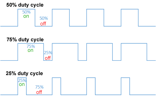
A pulse width modulated signal is a logic level signal of a fixed frequency, where the duty cycle, or width of the pulse, is changed or modulated to communicate a scalar value. Obligatory Wikipedia diagram below:

The new feature does what it claims to do, in that a subset of auxiliary pins can now be configured to output a PWM signal. If so configured, the duty cycle can be controlled using either the diagnostic or register protocol.

moteus configurable motor thermistors

When operating a moteus controller with a brushless motor there are two main things that can get hot: the FETs (field effect transistors) on moteus and the motor itself. By default, moteus has built in thermal throttling and fault detection if the FET temperature exceeds rated limits. In many configurations, the motor can be thermally connected to the moteus controller, so that the same FET temperature sensing can be used to prevent damage to the motor, but that isn’t always the case.

moteus firmware 2024-10-29

We’ve got a new firmware release for the moteus controllers up on github now, 2024-10-29! This update has a few new capabilities, a brief summary is below, while more detailed posts will come in the not too distant future:

MA600 Support: The MA600 from Monolithic Power Systems is an absolute magnetic encoder that uses a TMR (precision tunnel magnetoresistance) sensor. It is much more accurate with less noise than the AS5047P that moteus uses (or the MA732).

mjpower-ss

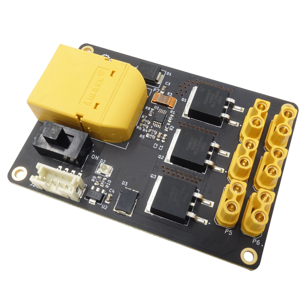
It’s another new product day here at mjbots! Introducing the mjpower-ss:

This provides many of the same functions as the power_dist r4.5b:

  • Pre-charge: High capacitance, low-impedance loads up to 4000uF will be safely turned on in a controlled manner.

  • Undervoltage and overcurrent protection: If the instantaneous current exceeds 100A, a soft circuit breaker is engaged.

  • Connector multiplexing: 1x XT90 input feeds 6x XT30 output connectors which are wired in parallel.

  • External switch: An external illuminated switch is supported, with the same connector and pinout as for the power_dist. A switch harness can be purchased separately.

Electrical power reporting with moteus

TLDR: As of firmware release 2024-05-20 moteus can now report a pretty good estimate of the electrical (and thus mechanical) output power going to the motor. You can get that through all the language binding options or in tview!

Background

Brushless motor controllers like moteus act like step down DC/DC converters. Their input is a higher voltage and low current, while the output to the motor is low voltage and higher current. If working properly, the output current is driven so as to produce torque at the output shaft.

hoverbot

I made a thing!

With that video out of the way, here is a bit more of a write-up!

Motivation

The hoverbot is a simple 2 wheel balancing robot. I built it to demonstrate how the moteus-c1 can be used to drive hoverboard motors and to demonstrate the capabilities of the pi3hat for high rate control and effective attitude reference calculation. It is powered by a single Bosch 18V cordless drill battery and controlled through an identical websocket based interface as the quad A1, primarily operated by a phone with a paired bluetooth joystick.

Wait for trajectory completion in tview

As of pypi 0.3.68, tview has gained the ability to delay execution of a compound command until the currently executing trajectory is complete. This can be useful for developing more complex motions that consist of multiple steps.

To use it, just issue a '?[optional_id]' in your command sequence. For instance, to move to position 1 and come to a stop, then move to position 0 when that has completed, you could do:

Debugging moteus calibration failures

When setting up a moteus controller with a new motor, you typically first run the automatic calibration sequence as documented in the reference manual. When your system is working well, that should be all that is necessary to enable moteus to perform accurate FOC based torque control of the motor. Then you can set up basic parameters and tune the position PID control loop. What happens though when the automatic calibration doesn’t work? This post shares the most common failure modes during calibration.