Archives: Moteus

pre-charge circuit

Next up in Super Mega Microbot 2’s existence is being able to run untethered.  Before that can happen, I need to be able to plug in a battery, and hopefully not have everything explode.  As seen with the IMU junction board, even minor inductive links can result in chips getting toasted.  I had thought that just adding sufficient capacitance to each of the point-of-load converters would resolve the issue, but in fact that almost made it worse.
rpi3 interface board

Now that I have a chassis that can walk a little bit, I need to get the onboard computer working.  To do that, I needed to update the raspberry pi 3 daughterboard I built for the previous turret for the new bus voltage and communication format.

The rpi3’s UART is incapable of controlling the direction line on the RS485 transceiver, so I added a small STM32 micro in line to control the transmit / receive direction.  It adds a little bit of latency, but testing the firmware I was able to get it down to only a byte’s worth or so.

First walking with gearbox chassis

Short recap: After building the quadruped with near-direct drive motors, I discovered that the lateral servos had insufficient position control authority to keep the robot standing up.  Thus I embarked on a now month long quest to design and build an integrated planetary gearbox.  At this point, I have enough gearboxes built for all the lateral servos, so it should be able to walk, right?

And tada!  It can!  Well, at least a little bit.  I’ve only spent a short while with the gearbox based chassis, and have a lot of work left to do.  However, here’s a quick video showing it walking around, slipping on a ruler, and almost falling over a few times.

Wiring up the gearbox chassis

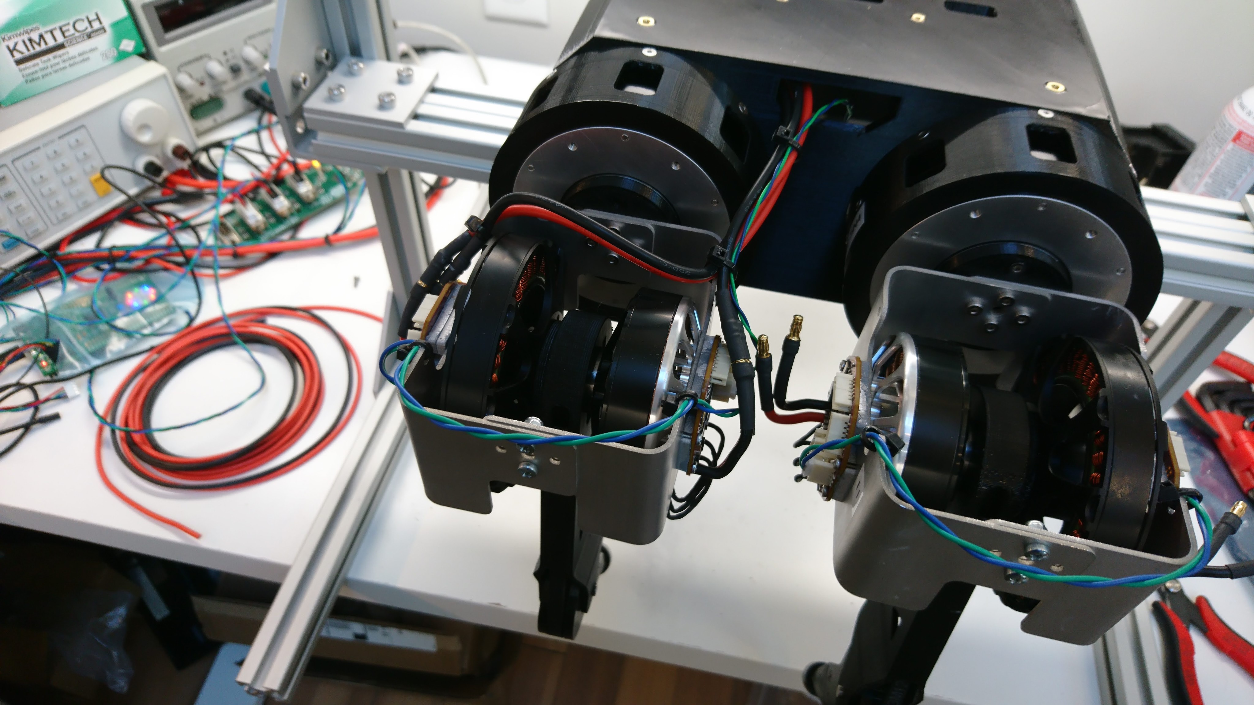
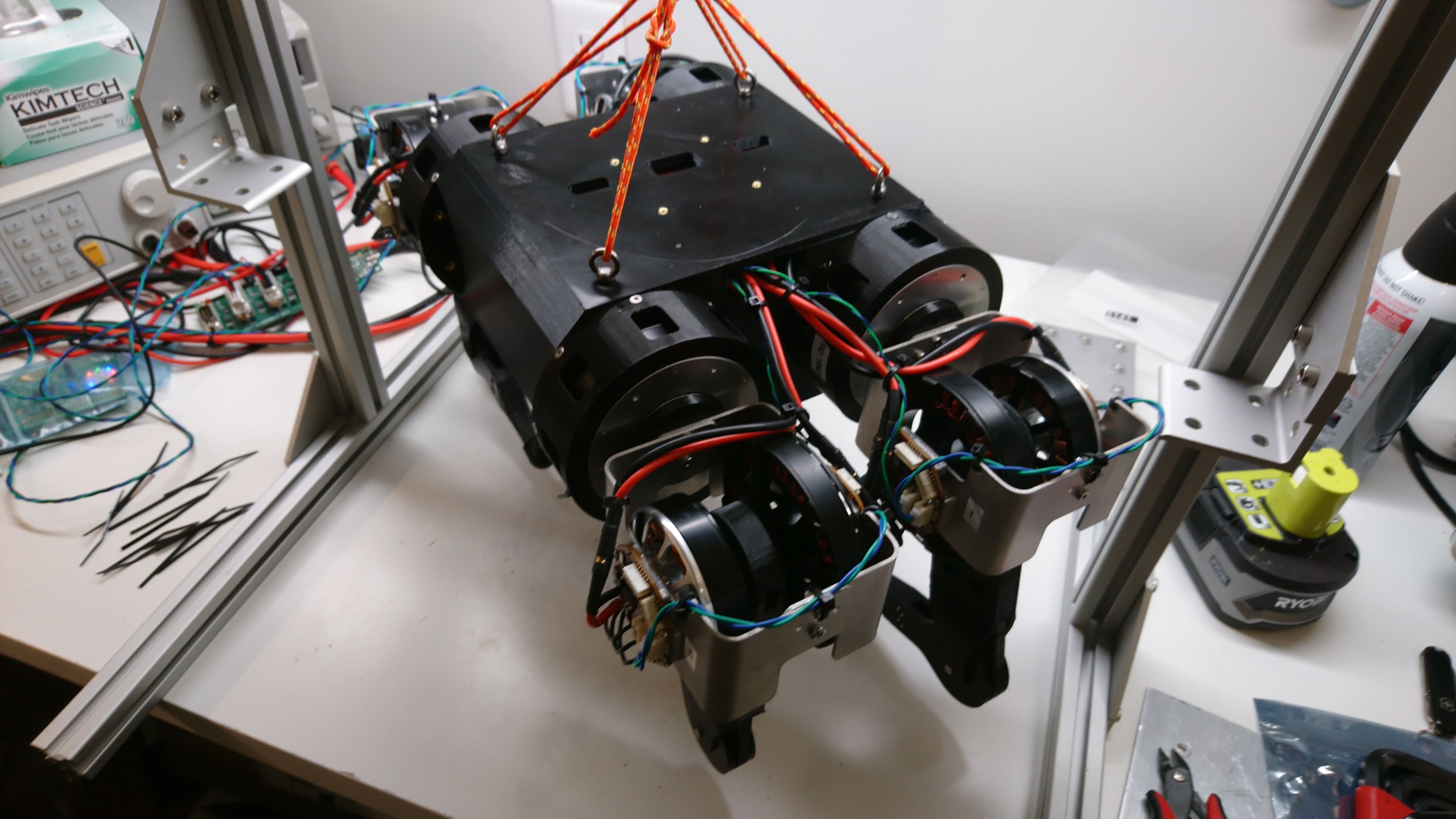
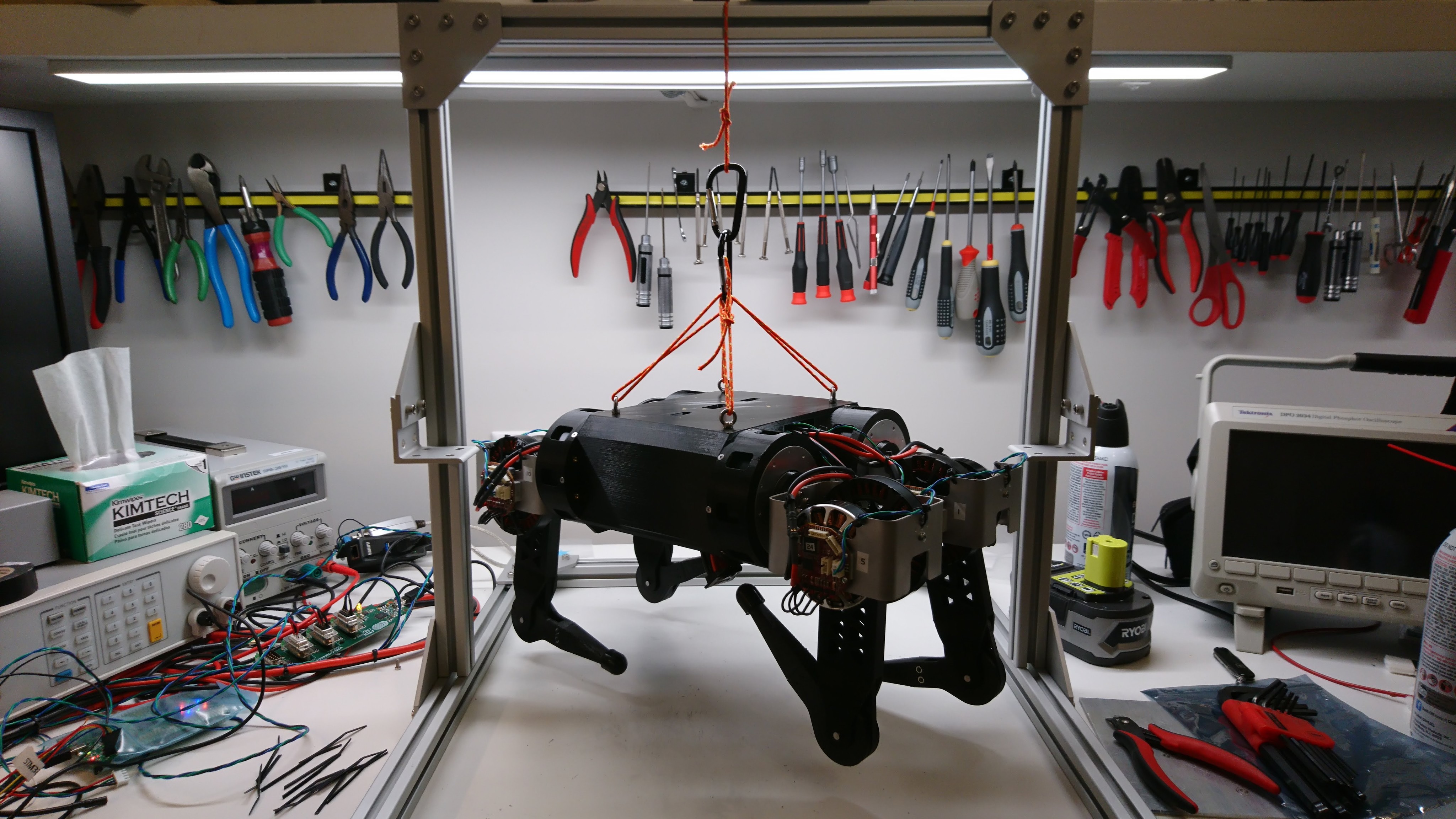
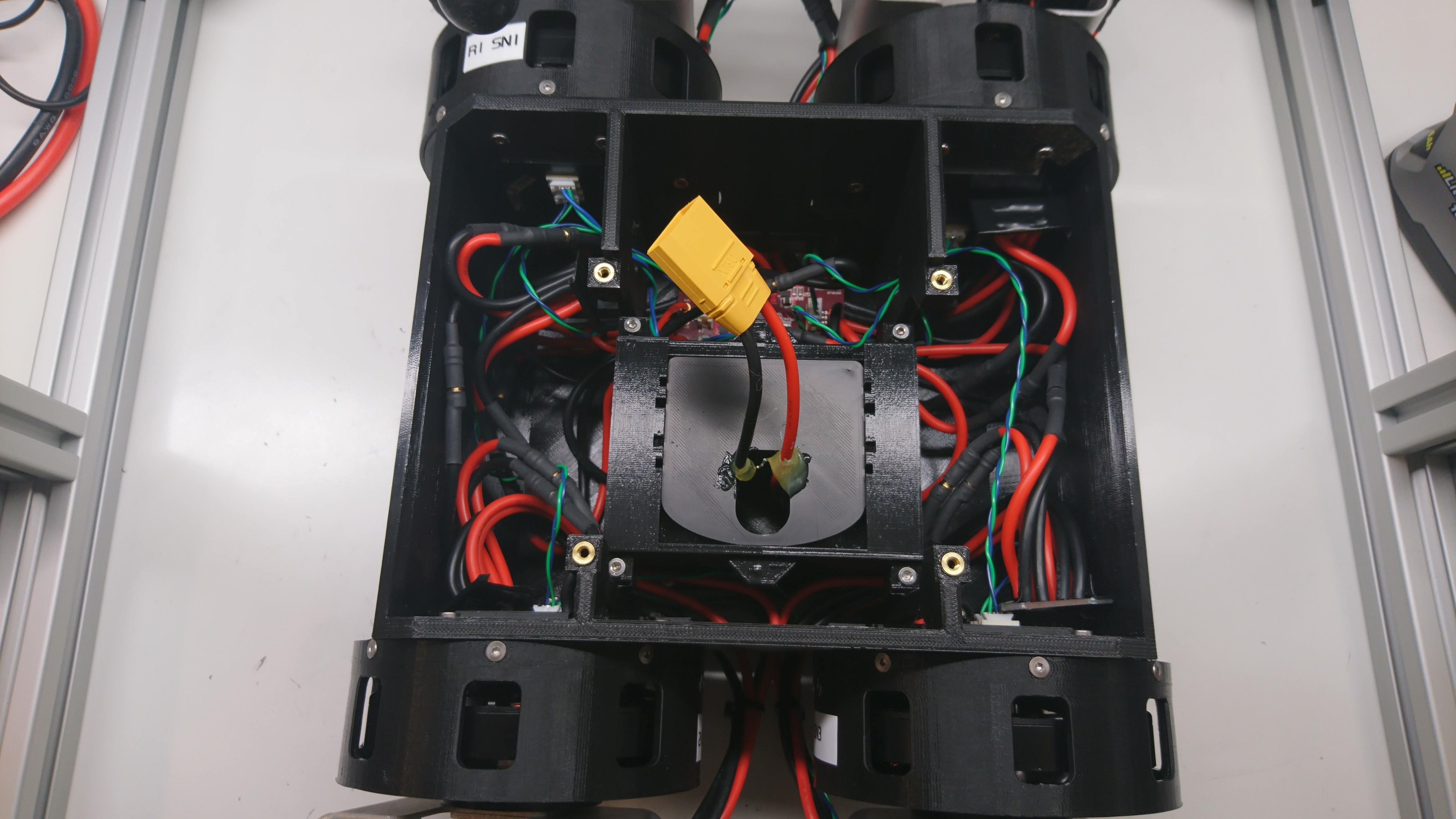
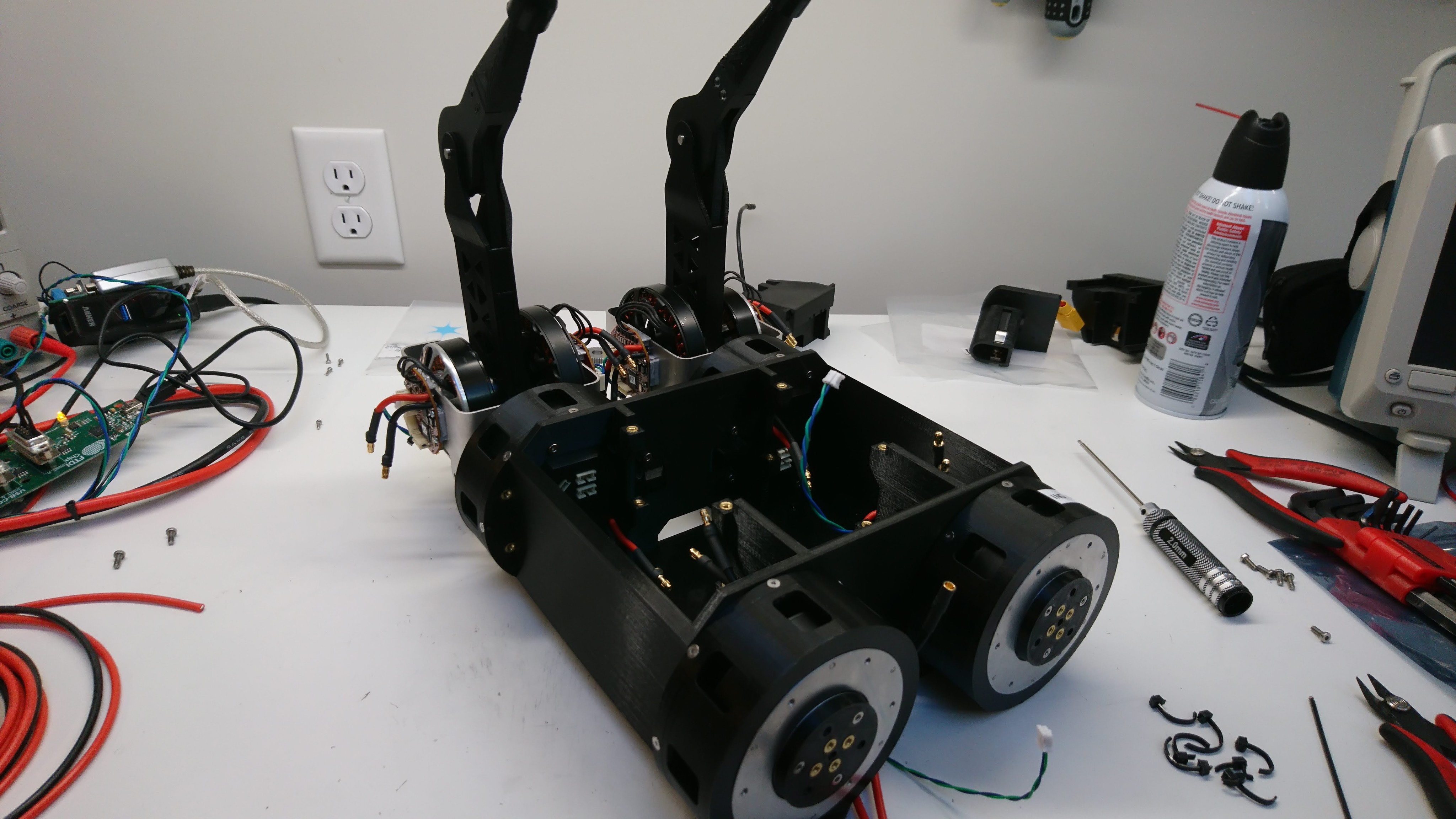
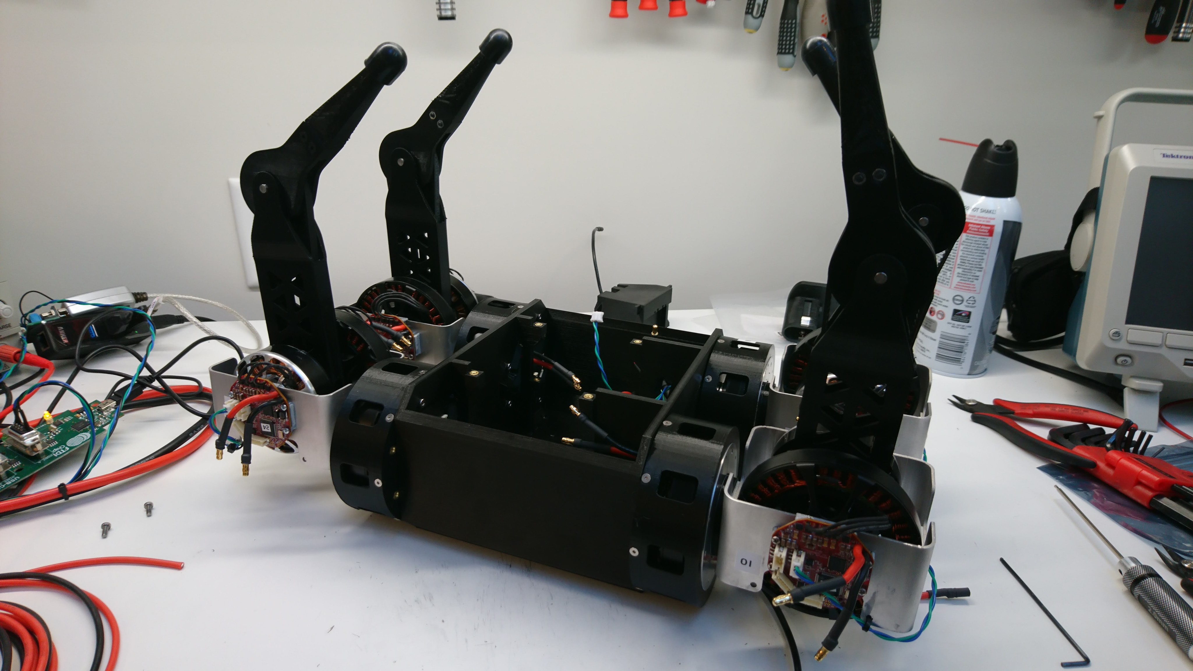
Now that I had a set of 4 at least minimally working lateral servos, I needed to wire up the chassis so that everything had power and data.  Here are some pictures of that process:

Two legs installed

Two legs installed

Four legs installed

Four legs installed

Joint cable routing

Joint cable routing

Times four

Times four

Suspended from the test fixture

Suspended from the test fixture

Four sets of busbars, the junction board, and a shore power battery simulator

Four sets of busbars, the junction board, and a shore power battery simulator

Lateral servo gearbox build(s)

After completing one gearbox, I needed to build at least 4 more of them to replace the lateral servos on Super Mega Microbot (2).  So, I got to work.  First, I disassembled 5 more BE8108 motors.

dsc_2140

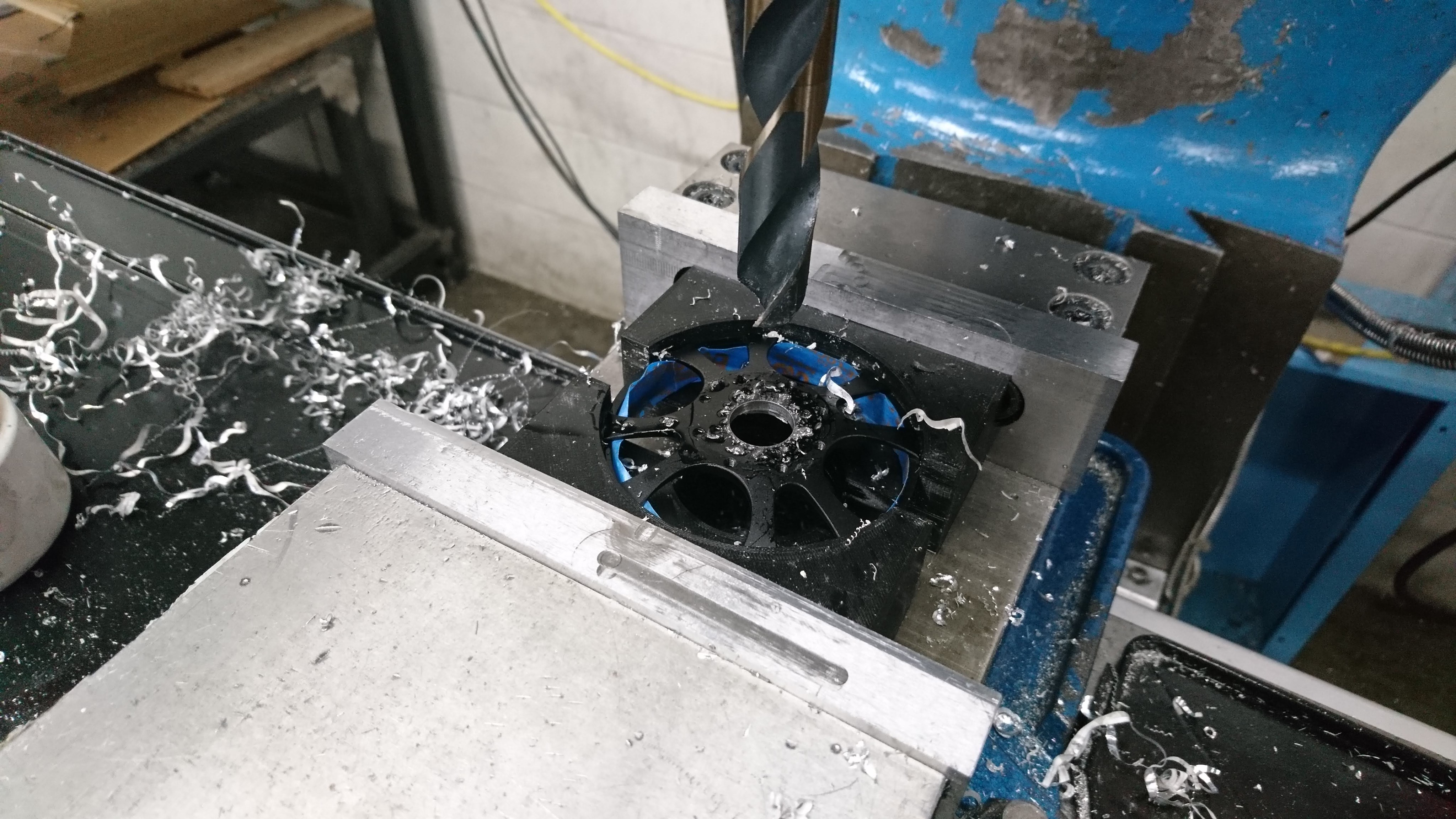
Then, I drilled out the rotors, this time using the mill at AA.

dsc_2145

Next I removed the stators from their backing.  This was painful enough last time, that I tried a new technique using the mill to do most of the work.  Unfortunately, one of the stators was critically damaged during my initial experimentation.  So, now down to 4 survivors.

Rebuild of gearbox assembly

After finally getting the darned thing apart, and printing a new outer housing, I went about re-assembling the whole mechanism.  This time, I tried to take care to make the future disassembly less painful.

To start with, I filed down the problematic outer bearing interfaces of the sun gear holder so that the bearings were a slip fit over them.  These two interfaces don’t need to be particularly snug, so that was easy enough, if monotonous, to accomplish.  I also machined out a some pockets around the magnet hole, to make it possible to just hot-glue the position magnet in place and more easily extract it.

Rotor and stator alignment

Last time I covered getting to the point of having the rotor installed into the gearbox.  Here we’ll look at making it actually work in that configuration.

When I first got the rotor in place, it was clearly not centered properly.  Although much closer than in the plastic gearbox, it did interfere with the stator during a portion of a revolution.  The first obvious problem was that the primary shaft wasn’t making it all the way through the front shaft bearing.  That should have been an easy fix, but for two different very annoying reasons.

CNC machined planet output and front housing

Shortly after receiving the sun gear holders, I received the first iterations of the planet output and front housing.

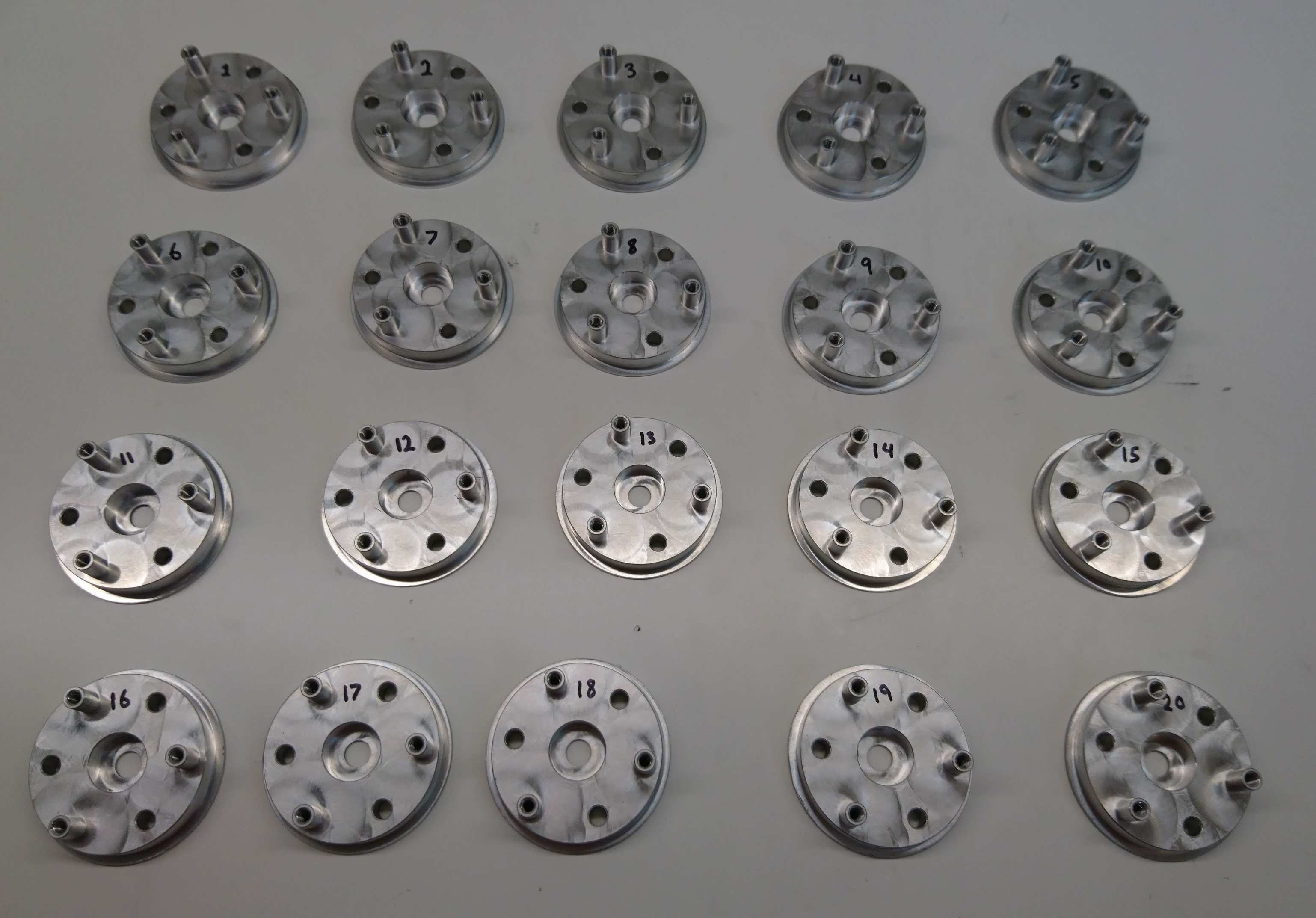
20x of the planet output

20x of the planet output

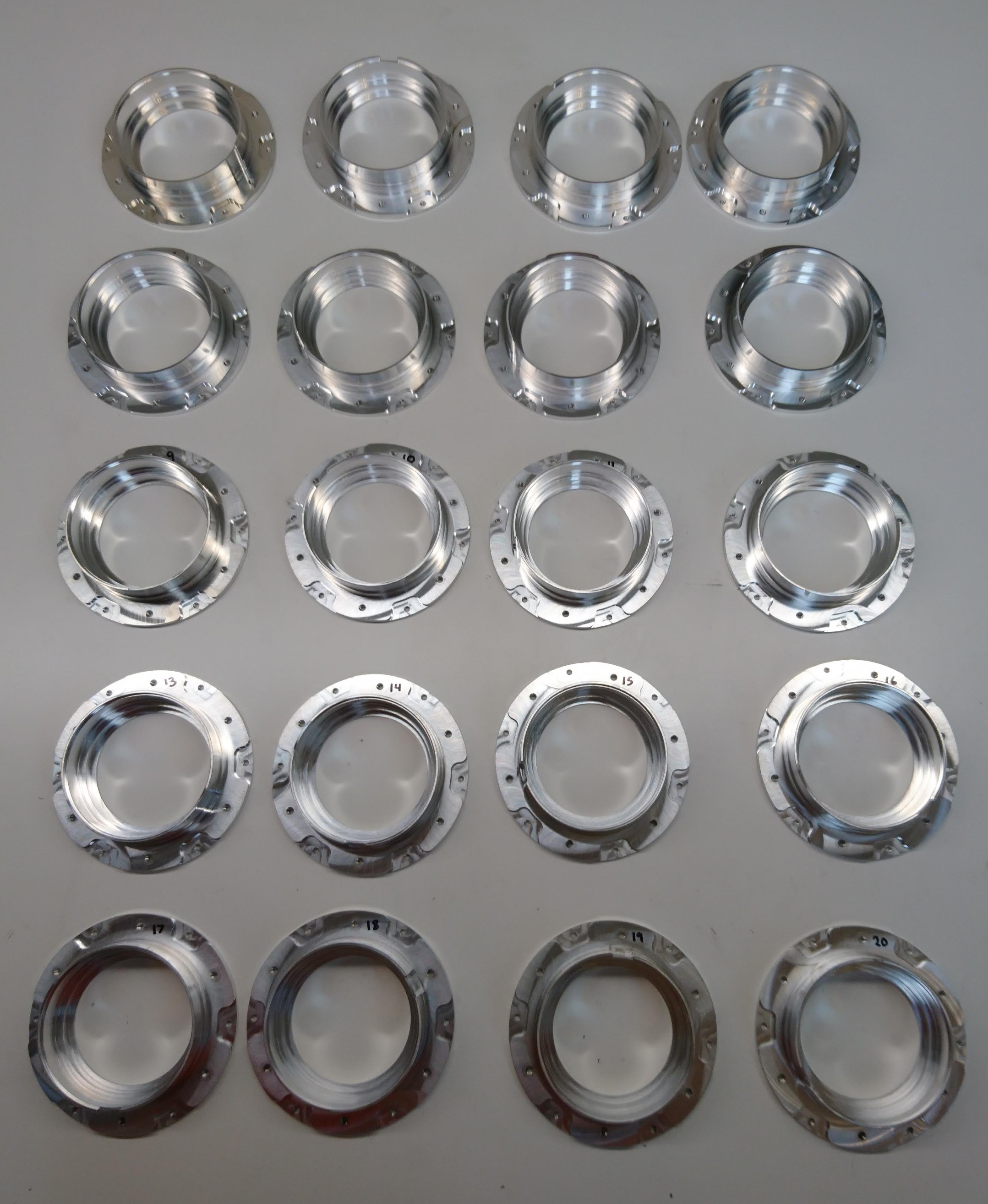
20x front housing

20x front housing

Both of these seem to have actually adhered to the tolerances I requested, so thankfully it won’t be too hard to fit everything together.  However, getting everything together for the first time did involve a comedy of errors – a lack of planning for assembly order, a lack of foresight into how things would be *dis-assembled*, a stubbornly stuck shaft, and plenty of broken parts.

Gearbox first CNC machined parts

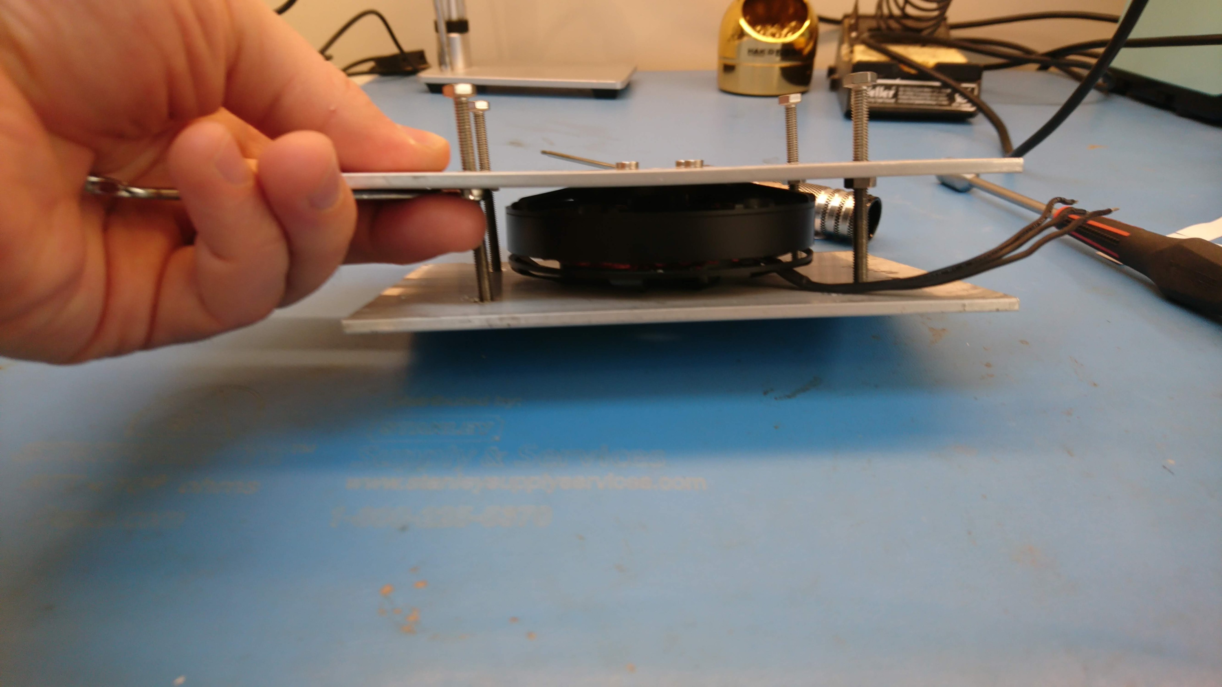
As seen in my draft plastic assembly, the required alignment between the rotor and stator in the gearbox is relatively tight.  The difference in diameter between the inner race of the rotor and the outer surface of the stator is only about 0.2mm, which gives 0.1mm of clearance in normal operating conditions.  A plastic drive train was never terribly likely to succeed.  My next steps have been to machine the pieces of the gearbox critical to alignment out of aluminum, so as to ensure that the rotor and stator, (and also the gears) are held within some approximation of appropriate tolerances.  The path of joints between the rotor and stator looks roughly like this: