Archives: Moteus

moteus servo mk2: Outer housing

The outer housing for the moteus servo mk2 is just a precision round tube with some mounting holes drilled peripherally.  Still, manufacturing it was slightly annoying, mostly because of my available machining resources.
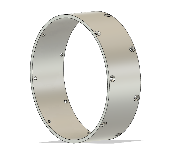
outer_housing_cad.png

Manufacturing

I started off with round tube stock with some extra margin on the inside and outside:
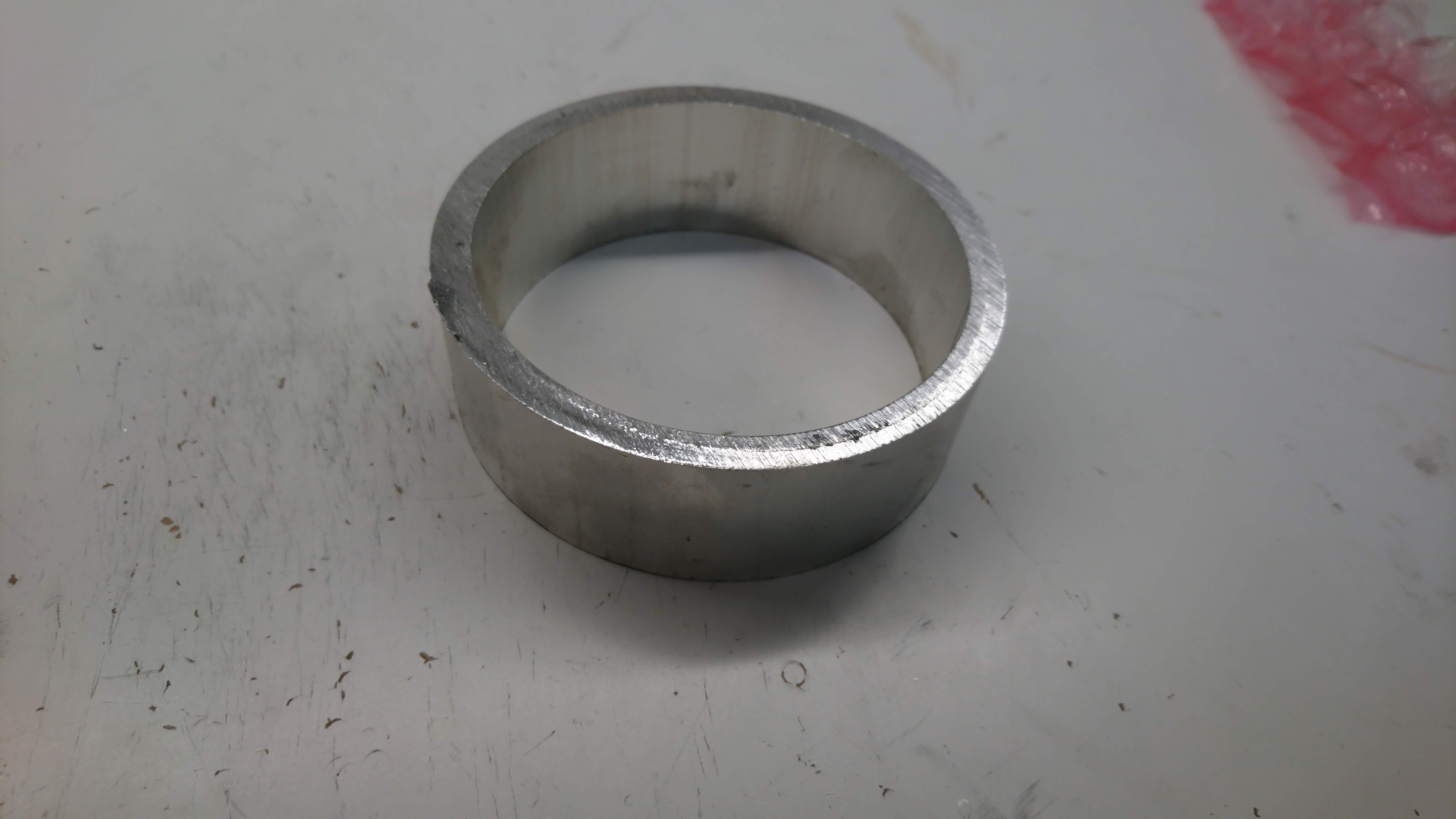
dsc_1789

Then I went and used the manual lathe at Artisan’s Asylum to get the correct ID, OD and length:
moteus servo mk2: Planet Input

As the first part of the new moteus servo mk2, and continuing in my series of learning about CNC by building parts for the quadruped, next up I machined the input to the planet gears on my Pocket NC V2-50.  This was a part, that for my quad A0 build, I used a 3d printed part in PETG as it is probably the least stringent part in the gearbox in terms of tolerances and load, although I still expect the plastic ones will likely wear and fail after some time with heavy use.

moteus servo mk2

As described in my roadmap, making a new revision of the moteus servo is up there on my list of things to do.  The initial servos were a work of art, yes, but also pretty fragile, very labor intensive, and still not all that robust.  My goals this time around are:

  • Manufacturability: The servo mk1 took about 2 or 3 man-days of manufacturing time per servo once all the steps were factored in.  I’d like to get that down to an hour or two at most per servo.
  • Robustness: The planet input, outer housing, back housing, and controller cover of the mk1 servo were 3d printed, mostly to save cost and time.  This necessitated adding reinforcing rings on the outer housing, as it is nearly impossible to 3d print something with the required material properties in a single print.  At this point, all of these components should just be made of aluminum like the others.
  • Repairability: Once the mk1 was assembled, there was no way to disassemble it, as installing the stator interfered with the ability to remove the outer housing, and the outer housing in place interfered with the ability to remove the stator.
  • Convenience: The mk1 servo used the r3.1 moteus controller, which had RS485 connectors sticking straight out the back, and bare power wires coming out the back.  That orientation for connecting things was not terribly convenient in the full rotation leg design, and required making extension cables.  The newer moteus controller has the connectors sticking out the bottom, so the servo needs to accommodate that.

CAD explosion

CAD rendering

CAD rendering

Ramping up for moteus servo mk2

Some time ago I put in orders for all the long lead time items on a second version of the moteus servo.  This is primarily aimed at improving the manufacturability and reliability, along with some minor performance improvements.  I’ve now got at least samples of all the long lead time parts in house!

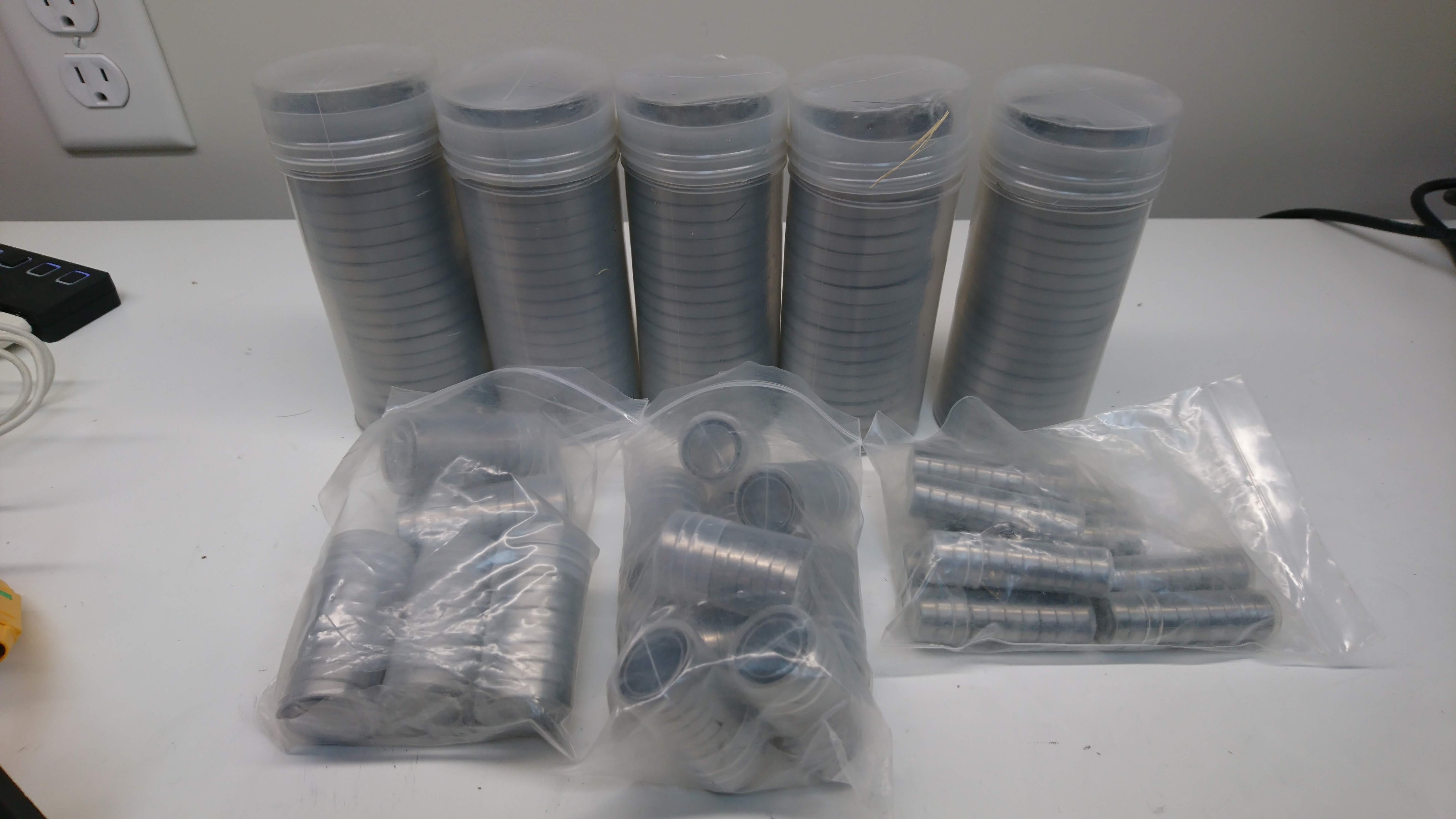
Loads of bearings

Loads of bearings

A lot of custom gears

A lot of custom gears

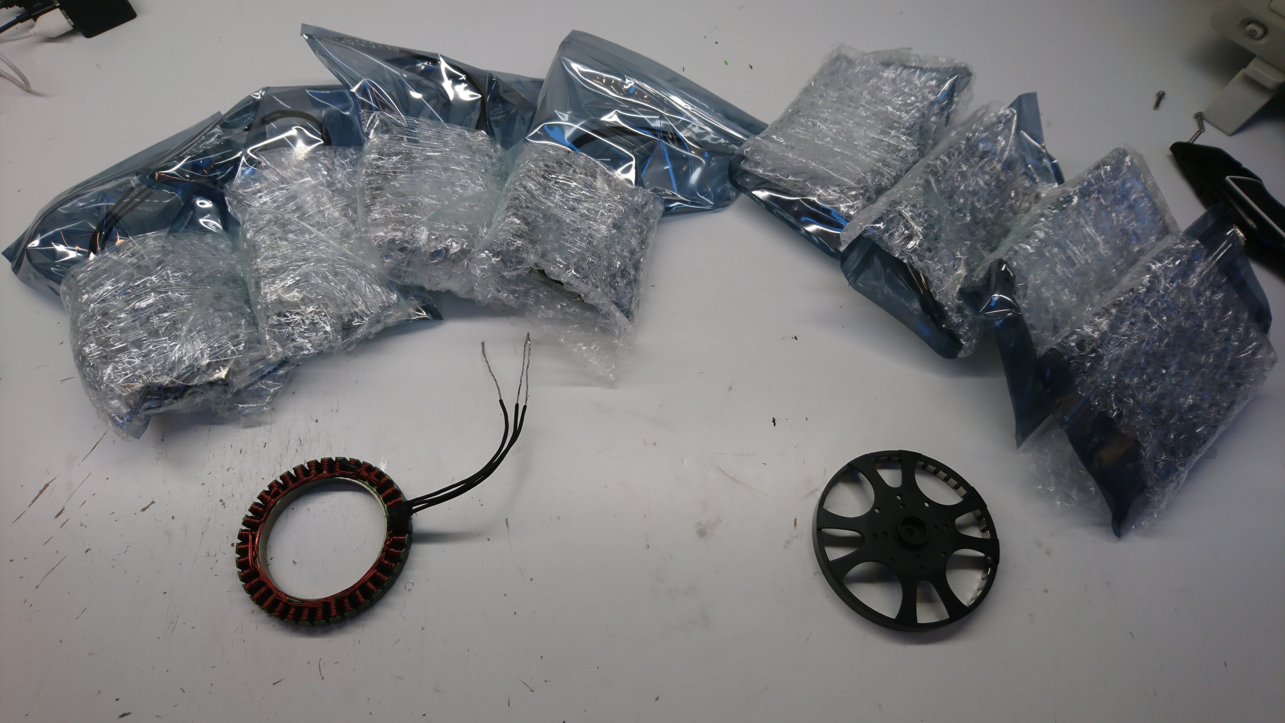
A sample batch of custom rotors and stators

A sample batch of custom rotors and stators

Flux braking with the moteus controller

When I was trying my first pronking, I kept having over-voltage issues when the servos were trying to dump power back onto the DC bus, no matter how high I set the voltage limit.  During that test, I was running with a nearly full battery, so my working theory is that the battery protection circuit was disconnecting the battery either because of too high a charging current, or too high a system voltage.  When the battery was disconnected, and the servos were still putting power onto the bus, that resulted in the voltage spiking arbitrarily high, followed by a total loss of power when they all faulted and then nothing was powering the bus at all.

shop.mjbots.com

In my quest to create a more dynamic quadruped, I’ve started accumulating a lot of parts from bulk buys that could be reasonably useful to other hobbyists and experimenters.  To maybe make life easier for everyone, I’ve started up what may be the worlds ugliest online shop where you can buy some of these components.  For now, I have some bearings and custom gears that are useful when building servos for dynamic robots.

quad A0 - Controlled jump

Now that I have a full rate inverse kinematics and dynamics solution, I can begin to do more interesting things.  A while ago I did the first jump on the quad A0 – in that video I used a limited technique just to verify that the platform was indeed capable of jumping.  The joints were commanded in an open loop fashion, and really only at the transition points of the jump sequence, relying on the control loops in the servo to actually achieve each stage of the jump cycle.  That resulted in the jump only being minimally controlled… tracking errors would result in the robot taking off from a not-level position and the timing was not super reliable to boot.

Full rate inverse dynamics on the quad A0

Last time I updated my inverse kinematics solution to also include dynamics, velocities and forces.  Now I’m in the process of integrating this onto the robot.

The old SMMB / HerkuleX control software commanded the servo positions in an open loop, which did not take into account the actual position of the joints in any way.  What I’ve done now is implemented a control flow where at each cycle the state of all 12 servos is sampled, then the control laws are applied based on that state, then the resulting commands are sent out.

mjbots discord server

Over the last couple of months, I’ve had an increasing number of people looking for help with self-built moteus controllers which is great!  However, until today there hasn’t been a great way to get help.  Blog comments fall off the front page quickly, and there is no real other mechanism.

Thus, I’ve created a discord server:

There you can chat about the moteus controller, servo, or the quada0 and get feedback and help in closer to real time.  Thanks for collaborating!

Failing more gracefully

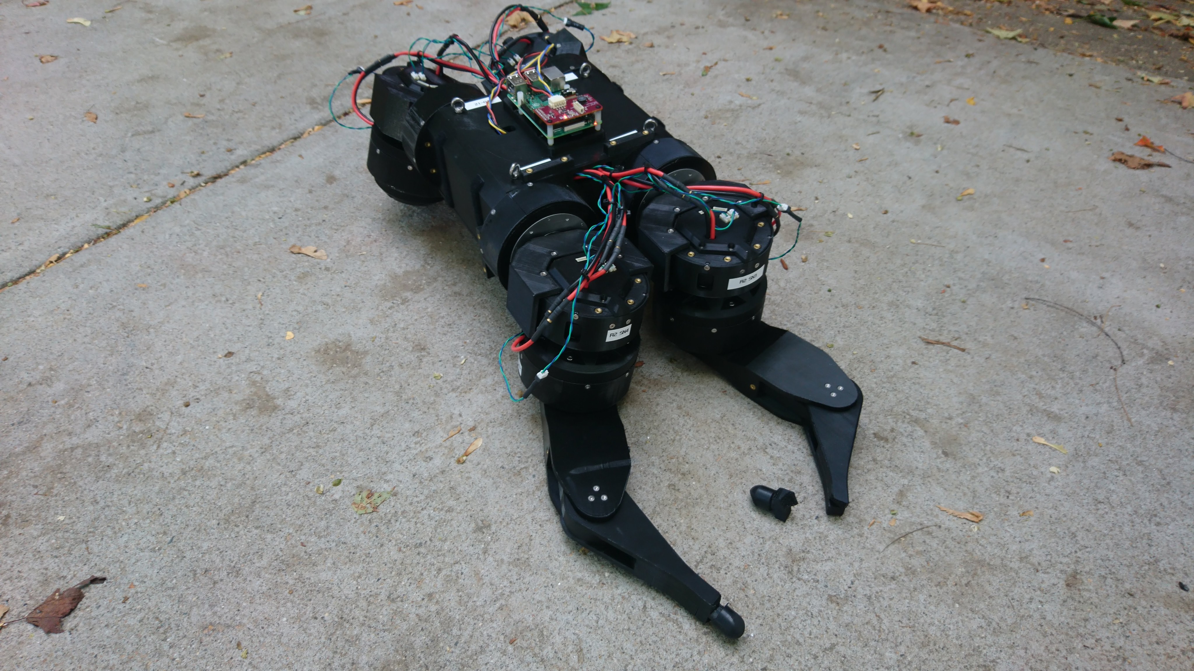
My outdoor filming for the project update video was cut short when the machine cut power to the motors, fell down, and one of the legs snapped off.  Fortunately, I already had plenty of footage when that happened, so it didn’t really impact the video.

Robot down

Robot down

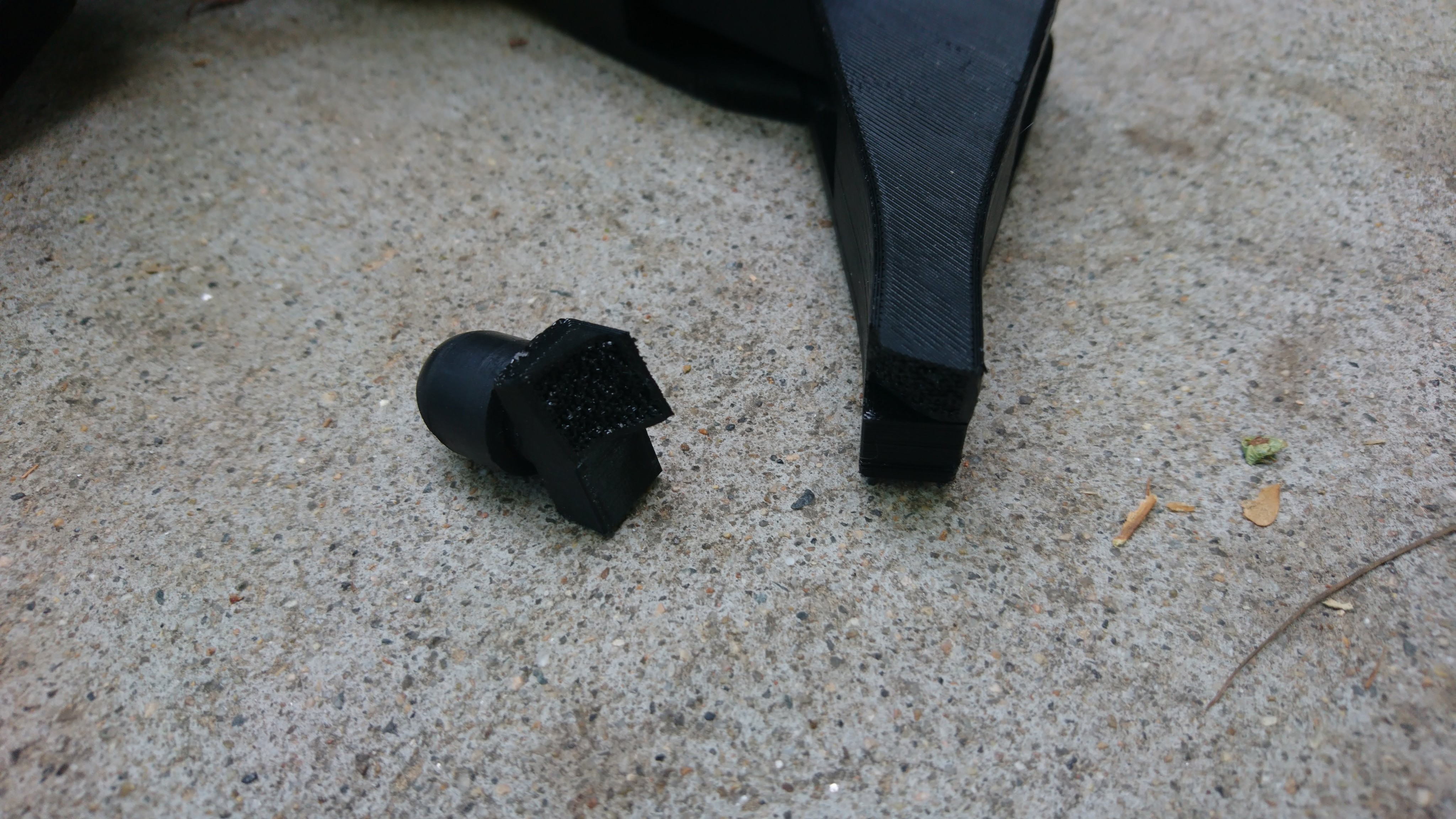
Nice infill shot

Nice infill shot

First, this demonstrates the not too surprising fact that this particular part of the leg design could use to be improved.  Second, and the topic of this post, is improving what the machine does when the inevitable failure does occur.