Lots of frameless stators and rotors
While gearing up to make some dev-kits followed by a pre-production run of the moteus servo mk2, I recently received a bunch of frameless rotors and stators.
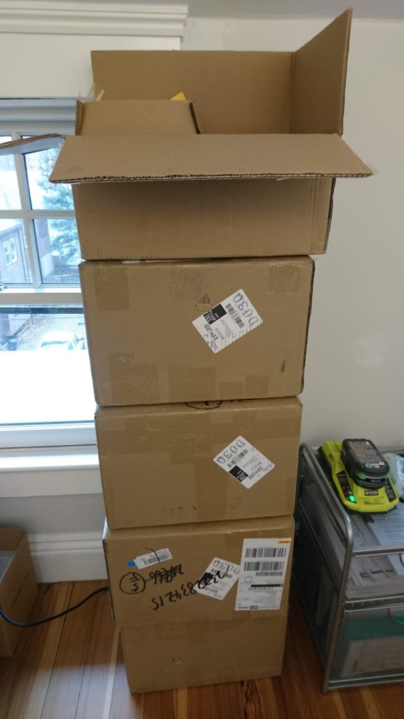
It’s almost taller than me!
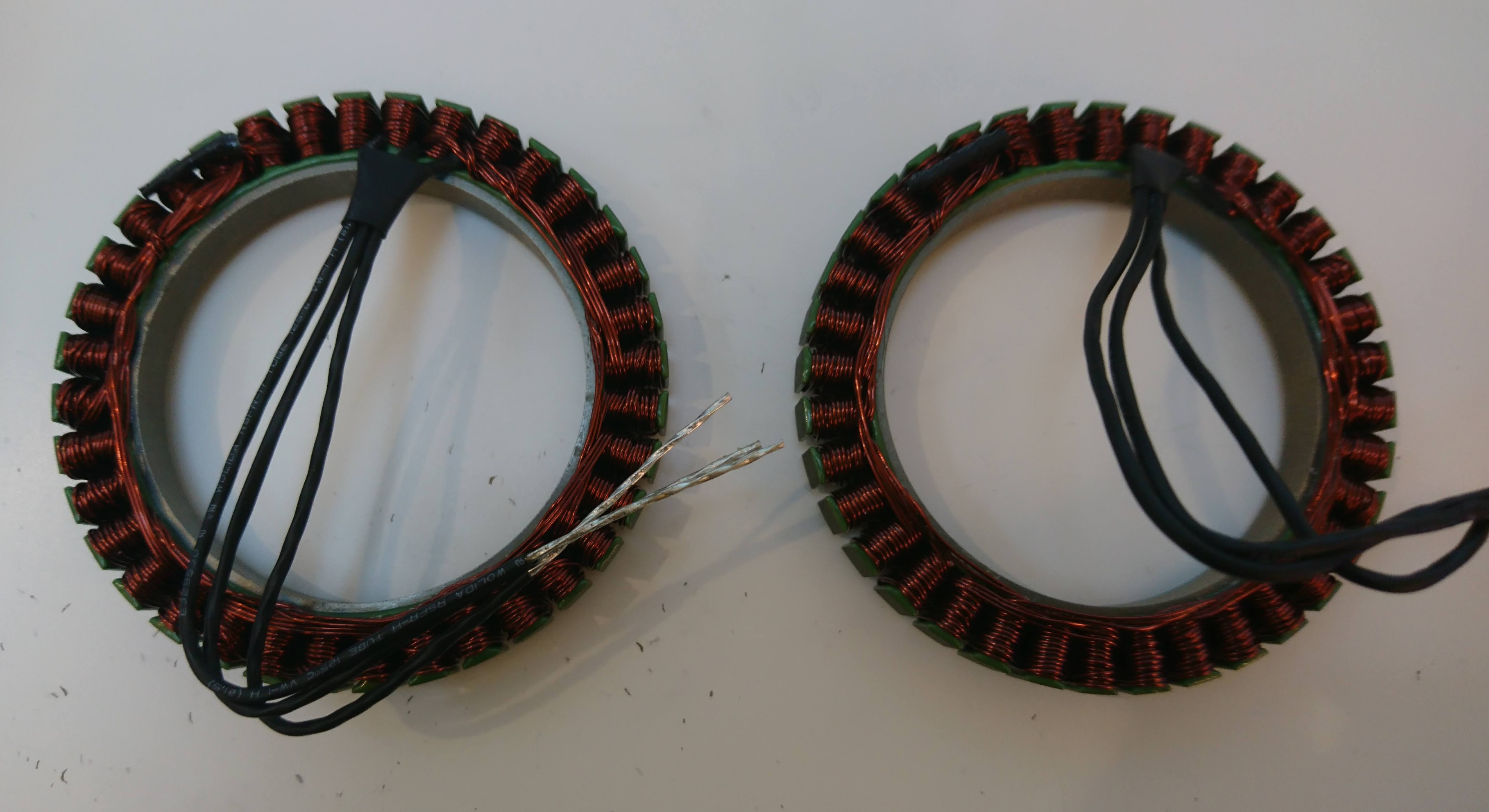
Some stators
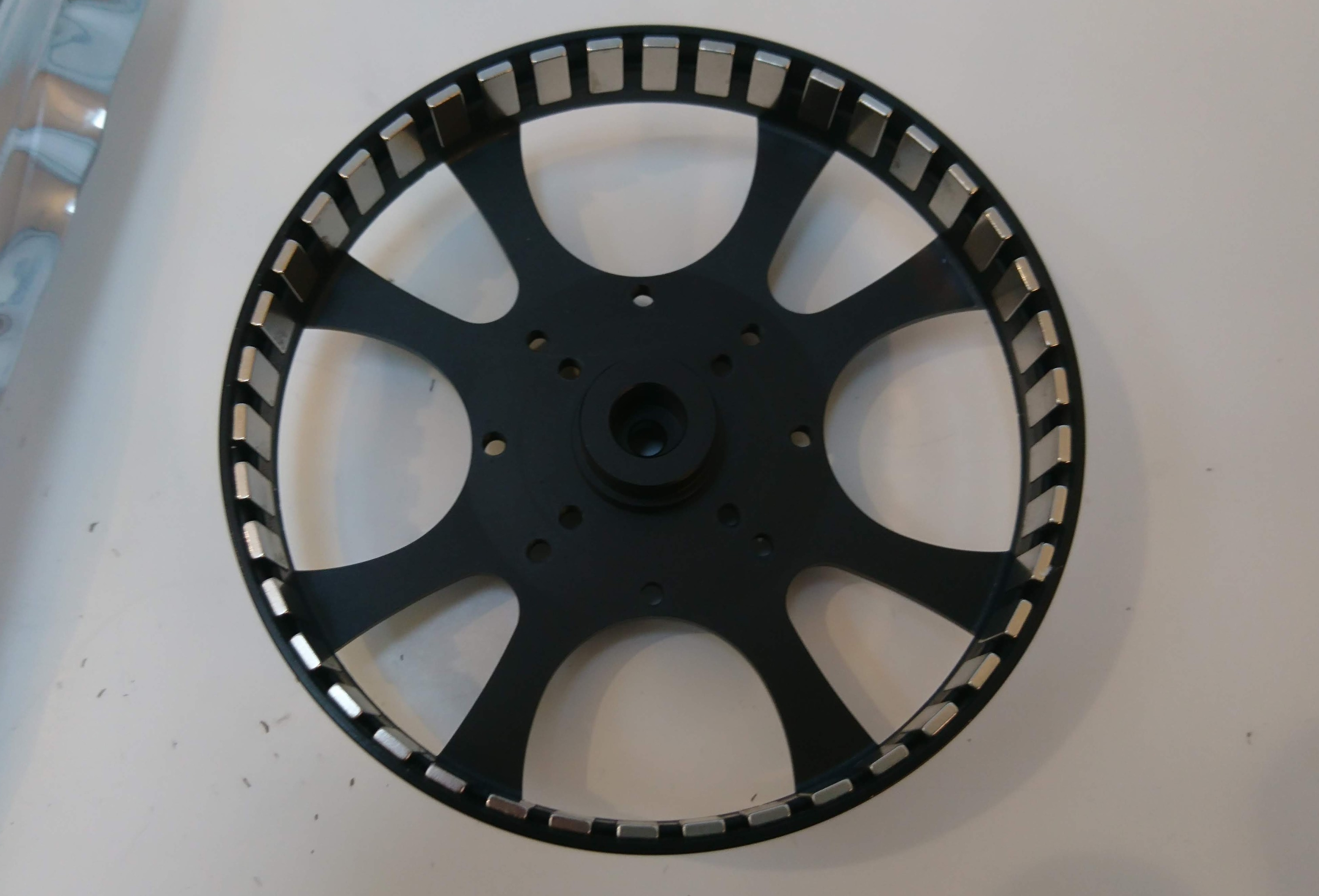
A rotor
As with the other custom items, I’ve got some spares of these for sale at shop.mjbots.com if you’re building along with me! [UPDATE no longer!]
Now it’s time to start building some servos!