Archives: Quada1

Another foot failure

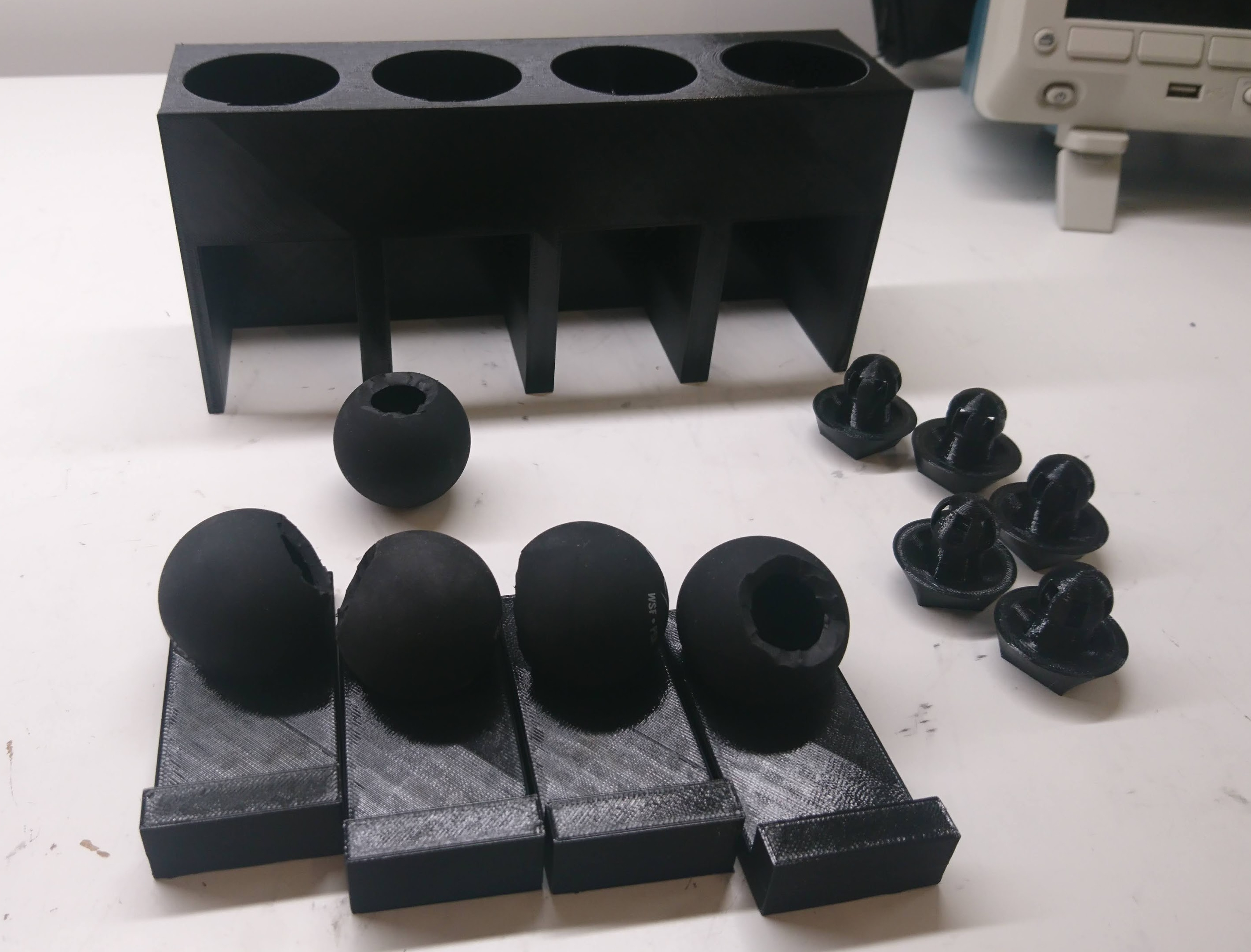
The first feet I built for the quad A0 lasted for maybe an hour of walking before snapping off. The current design, has been much more robust - completing a lot of intensive walking and jumping. However, all things must fail:

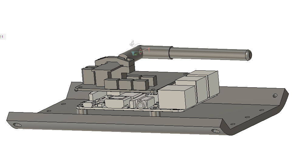
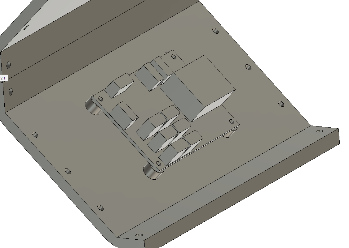
Looking at the failure, I was surprised I used so little material in the region in question. For now, I just made it 4x thicker and we’ll see how long that lasts, although ultimately it may need to be a different design or machined instead of 3d printed.

Cartesian leg PD controller

As I am working to improve the gaits of the mjbots quad A1, one aspect I’ve wanted to tackle for a long time is improving the compliance characteristics of the whole robot. Here’s a small step in that direction.

Existing compliance strategy

The quad A1 uses qdd100 servos for each of its joints. The “qdd” in qdd100 stands for “quasi direct drive”. In a quasi direct drive actuator, a low gearing ratio is used, typically less than 10 to 1, which minimizes the amount of backlash and reflected inertia as observed at the output. Then, high rate electronic control of torque in the servo based on current and position feedback allows for dynamic manipulation of the spring and dampening of the resulting system.

Improved swing trajectory

Now that I finally have tplot2 working sufficiently to diagnose problems in 3D, it is time to start actually fixing those problems. The first obvious thing I noticed when watching data replay was that the legs scooted around a lot after making contact with the ground. Absent 3D visualization, I knew something was wrong, but couldn’t easily tell what.

Diagnosing the first problem

Once I was able to plot the commanded position and velocity trajectory, I could clearly see a number of problems. For one, the trajectory was not terribly achievable. The velocity jumped in a discontinuous manner between different phases of the swing cycle, which resulted in large tracking errors when moving the physical legs:

Primitive derived fields in tplot2

One of the features that I wanted to get working in the newer tplot2 is some facility for rendering values which are calculated from the things in the log, even if not directly logged there. Straightforward simple cases would be things like the lengths of vectors, unit conversions, or quaternion to euler angles. You could imagine needing arbitrarily complex values plotted after the fact.

In past systems I’ve designed, I built in a generic scripting interface to allow arbitrary things to be plotted. I’d like to do that here as well eventually, but in the short term I had a need to plot the total normal force exerted on the ground by all stance legs. And I didn’t want to spend a lot of time designing a generic mechanism. Thus, I rigged up a very primitive C++ only mechanism, where a function can be registered which returns an arbitrary serializable structure. That is then rendered in the tplot2 tree view in a dedicated area, and has a pretty “hacky” way of getting its values on the plot if necessary.

Video and telemetry synchronization (diagnostics part 8)

This is part of a continuing series on updated diagnostic tools for the mjbots quad A1 robot.  Previous editions are in 1, 2, 3, 4, 5, 6, and 7.  Here I’ll be looking at one of the last pieces of the puzzle, synchronizing the video with the rest of the telemetry.

As mentioned previously, recording video of a robot running is an easy, cheap, and fast way to provide ground truth information on all of the sensors and actuators.  However, it is only truly useful if it can be accurately synchronized in time to the other telemetry streams for the robot.

3D rendering in tplot (diagnostics part 7)

In previous posts of this series, I covered some diagnostics improvements I’ve made to help work on more advanced gaits for the mjbots quad A1 (1, 2, 3, 4, 5, 6).  This post will cover the last major new piece of diagnostics I added to tplot2, 3d rendering of telemetry data.

3D rendering

While it should be obvious, I’ll give a little exposition.  tplot2 in its state prior to this could show a “tree view” of all data logged in numeric form.  It had a “plot view” which let you plot any single floating point scalar vs time.  As of recently, it could also render video associated with a given point in time in the log.  However, as anyone who has ever tried to debug a 3d dimensional software application, much less a 3d dimensional robot, can attest, debugging with scalar numbers and time plots is only productive for a very limited range of problems.

Log file format (diagnostics part 4)

In parts 1, 2, and 3 I covered some motivation for the updated mjlib diagnostics system and the serialization of individual structures.  In this post, I’ll cover how those structures are written into a file from an embedded system like a robot and how diagnostic tools can access them efficiently.

Goals

The top level goals are:

  • Efficient to write live from an embedded system: The quad A1 generates log data currently at 400Hz, consisting of hundreds to thousands of telemetry data points in every update.  It does this on a relatively low-end raspberry pi 3b+.  The format should be able to support writing data at high rates without a significant CPU burden.
  • Efficient seeking by time and record: Readers of the file should be able to efficiently seek by time in the stream, as well as extract all of a single record without having to process unnecessary data from the log.
  • Self contained: While this property  in the log comes from the underlying mjlib serialization format, it is worth re-iterating here.  All information necessary to return a JSON or CSV like structure for each instance should be present within the log.

Design

The detailed design of the log format is documented at README.md, here I will give a brief summary.

Updated serialization library (diagnostics part 1)

Now that I have the qdd100 servo in beta phase, the IMU working at full rate, and the quad A1 is moving around I’m getting closer to actually working to improve the gaits that the machine can execute.  To date, the gaits I have used completely ignore the IMU and only use the feedback from the joints in order to maintain force in 3D.  With tuning and on controlled surfaces this can work well, but if you go outside the happy regime, then it can undergo significant pitch and roll movements during the leg swing phase, which at best results in a janky walk, and at worst results in oscillation or outright instability.

Quad feet construction fixture

The quad A1 was the first robot I built with foam cast feet.  When I did the first feet, I jury rigged a fixture from some old toilet paper rolls to hold things in place while they were curing.  When I went to rebuild with my most recent leg geometry, I figured it was time to get at least a little more serious.  Thus, my new leg casting fixture:

dsc_0578

When an insert is cast into place, it is set on one of the trays, the tray is inserted into a slot, and then a weight can be placed on top and constrained by the fixture.

quad A1 chassis updates

I finally got around to fixing a number of minor glitches in the quad A1’s chassis recently.

1. The raspberry pi is now far enough away from the left panel that you can connect the HDMI if you choose.

20200506-rpi_mounting

2. I no longer have vestigal studs for the pre quad A0 junction board on the other side.

20200506-power_dist

3. The switch got moved down to between the legs.

dsc_0631