Archives: Nrf24l01

New product Monday: pi3hat

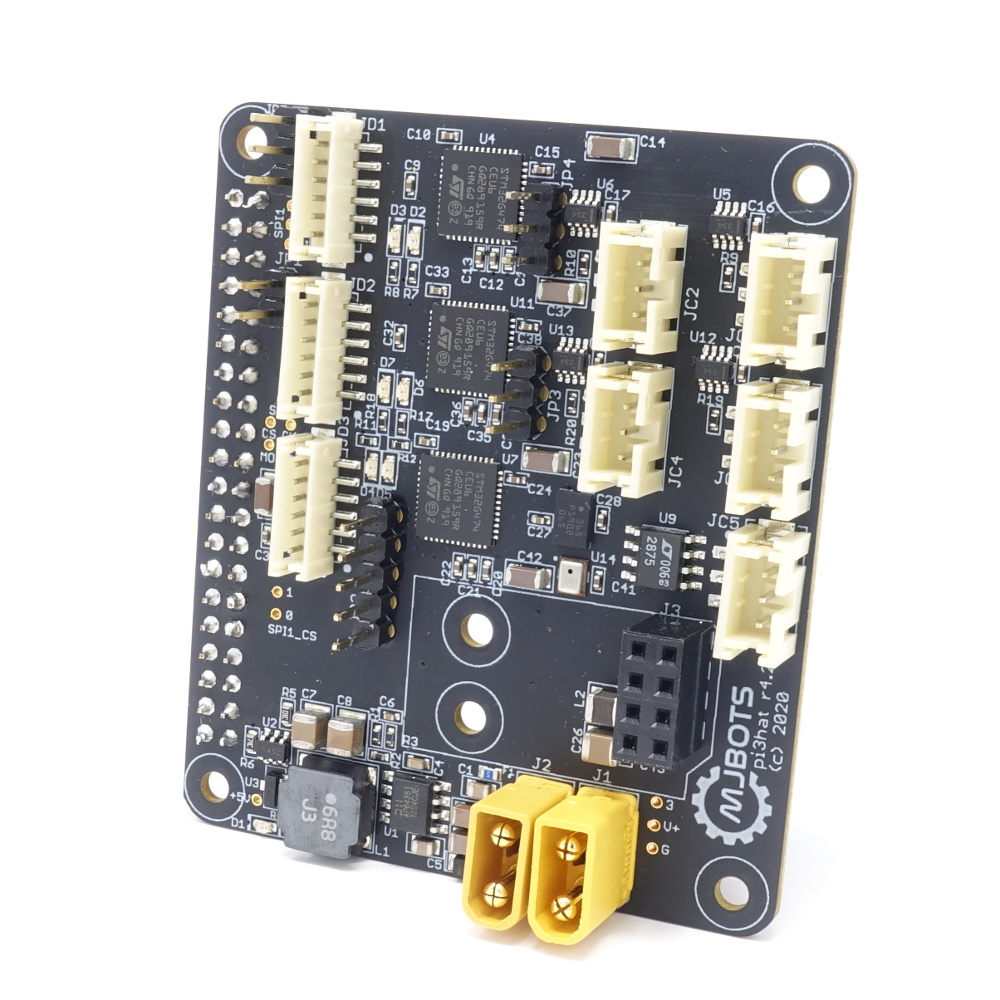
I’ve now got the last custom board from the quad A1 up in the mjbots store for sale, the mjbots pi3 hat for $129.

This board breaks out 4x 5Mbps CAN-FD ports, 1 low speed CAN port, a 1kHz IMU and a port for a nrf24l01. Despite its name, it works just fine with the Rasbperry Pi 4 in addition to the 3b+ I have tested with mostly to date. I also have a new user-space library for interfacing with it that I will document in some upcoming posts. That library makes it pretty easy to use in a variety of applications.

Updated quad pi3 hat

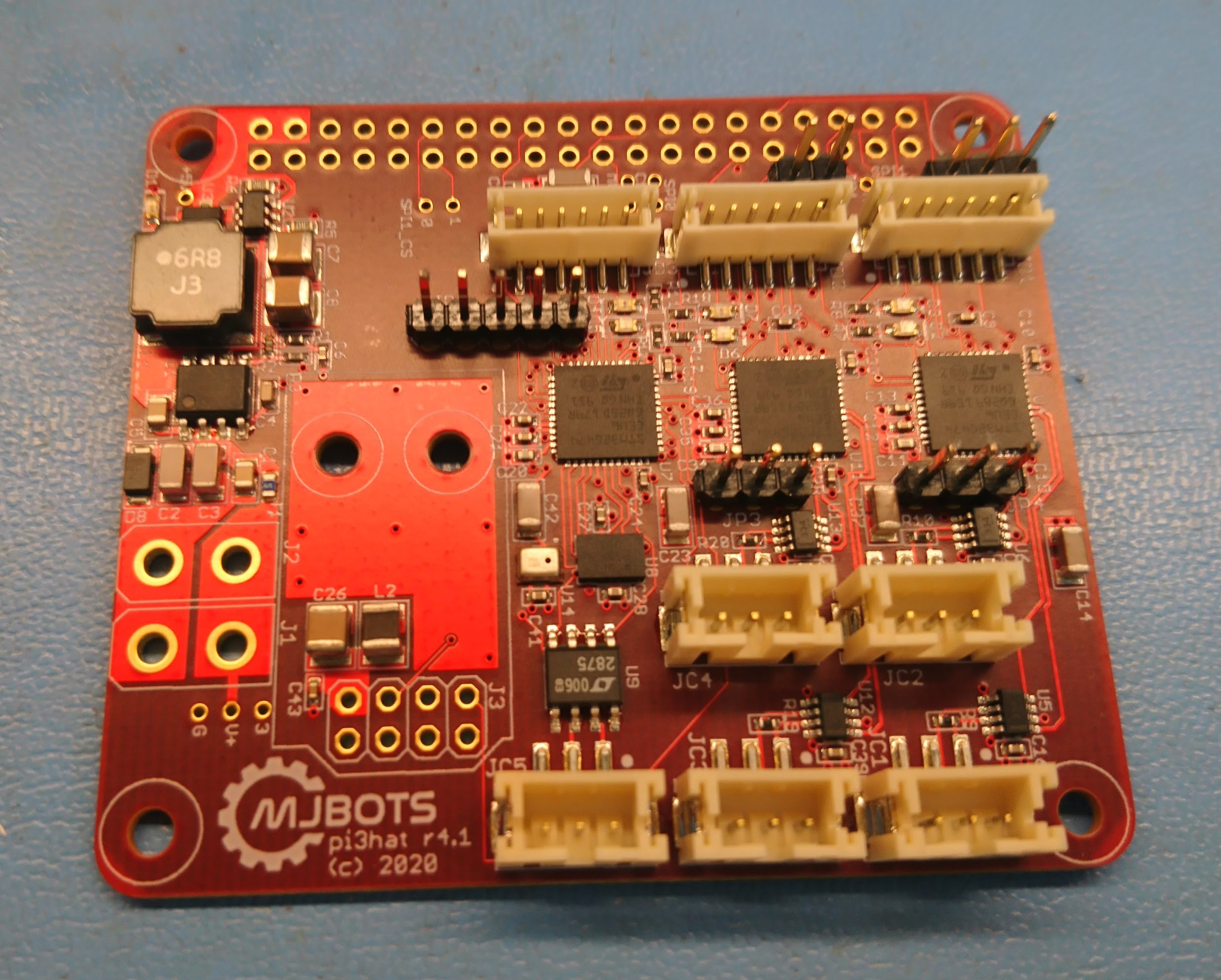
I made a number of tweaks to the quad A1’s raspberry pi hat to get it ready for production, resulting in r4.1 of the board:

dsc_0491

None of the changes were particularly big, but each has some value:

  • The correct switch mode regulator is installed.
  • The auxiliary CAN transceiver was switched to one that supports a larger common mode voltage.  This will allow it to be connected to the power distribution board without smoking.
  • Each of the STM32s now has some GPIO pins connected directly to GPIOs on the raspberry PI primarily to be used for interrupts.
  • Pin headers expose a few gpio pins from each STM32 for interfacing with random external things.
  • The NRF radio module changed orientation and has improved power filtering.
  • I added a microphone to the auxiliary STM32.  The goal is to eventually be able to use that to synchronize external video with onboard data collected during operation more easily.

I’ll bring this up in a future post!

Spread spectrum integration

I’ve been developing a new bi-directional spread spectrum radio to command and control the mjbots quad robot.  Here I’ll describe my first integration of the protocol into the robot.

To complete that integration, I took the library I had designed for the nrfusb, and ported it to run on the auxiliary controller of the pi3 hat.  This controller also controls the IMU and an auxiliary CAN-FD bus.  It is connected to one of the SPI buses on the raspberry pi.  Here, it was just a matter of exposing an appropriate SPI protocol that would allow the raspberry pi to receive and transmit packets.

Spread spectrum implementation

With a protocol design in hand, the next step was to go and implement it.  My goal was to produce a library which would work on the nrfusb, and also on the auxiliary stm32g4 on the mjbots pi3 hat.  In this first implementation pass however, I only worked with the nrfusb as both transmitter and receiver.

While developing this, I had more than my share of “huh” moments working from the datasheet and with the components.  To begin with, the initial nrf24l01+ modules I got were all Chinese clone ones.  While I was having problems getting auto acknowledgement to work, I discovered that the clones at a minimum were not compatible with genuine Nordic devices.  Thus I reworked genuine parts into the modules I had:

Spread spectrum protocol design

Last time I discussed the rationale for building a custom control and telemetry solution.  Here I’ll describe the protocol design a little bit, before discussing the implementation in a future post.

Frame design and frequency hopping

The basic idea is that the transmitter sends a frame to the receiver every 20ms, and each frame is sent on a different radio frequency.  A set of frequencies and their order is generated pseudo-randomly based on a “key” that the transmitter and receiver each share ahead of time.  The receiver replies on the same frequency with its telemetry.  Then the transmitter and receiver each switch to the next frequency in the list to get ready for the next frame.

Spread spectrum RF control and telemetry

Now that I have both sides of the nrf24l01+ link covered, it was time to design a protocol to take advantage of them.

Design space

To recap, what I needed was a reliable means of commanding the robot and receiving telemetry, even in congested radio environments.  At competitions or events like Maker Faire, Robogames and such, the wireless environment is often totally trashed.  Hundreds of devices are operating in close proximity, across all spectrum bands, including plenty of things that probably aren’t licensed to be transmitting in the first place.  When we first built Super Mega Microbot, we used a custom protocol with a 5 GHz wifi transmitter as the physical layer and selected USB based dongles which allowed control over the physical layer.  USB proved problematic, and with national RF regulations, it is extremely challenging to find wifi devices which provide that level of control at the RF layer.  Also, even with full physical layer control, wifi is difficult to make work in a reliable manner as there is so much congestion in both the 2.4GHz and 5GHz bands and the channels are so wide.

nrfusb

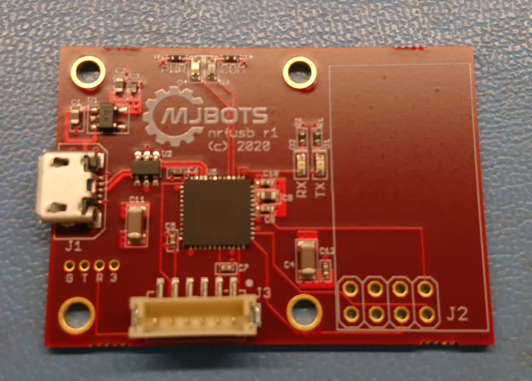
In order to bring up the final piece of the raspberry pi 3 hat, the nrf24l01+, I wanted a desktop development platform that would allow for system bringup and also be useful as a PC side transmitter.  Thus, the nrfusb:

dsc_0367

Similar to the fdcanusb, it is just an STM32G474 on the USB bus, although this has a pin header for a common nrf24l01+ form factor daughterboard.

The next steps here are to get this working at all, then implement a spread spectrum bidirectional protocol for control and telemetry.