Archives: Moteus_n1

MA732 encoder support for moteus

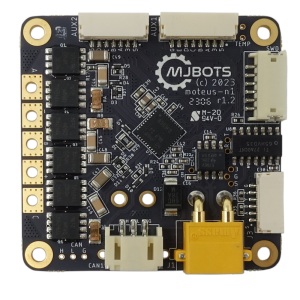
As of release 2023-09-26, moteus r4 and moteus-n1 now both support the MA732 as an external SPI encoder. The magnetic sensing performance of the MA732 is normally a bit worse than the AS5047P that is used as the onboard encoder with moteus, but it has two possible advantages.

The first, is that it is much smaller, using a 3mm x 3mm QFN package. The second is that it supports off-axis applications. You will need to read the datasheet, and set the 'aux?.spi.bct' configuration parameter correctly, but this can enable operation in interesting geometries, like a ring magnet with a hollow shaft, or where the coaxial placement is otherwise not feasible.

New "hold position" watchdog timeout mode for moteus

For a while now moteus has had the ability to configure what action takes place upon a CAN message watchdog timeout during position control mode. If configured with ['servo.default_timeout_s'](https://github.com/mjbots/moteus/blob/main/docs/reference.md#servodefault_timeout_s) moteus requires that CAN messages be sent at a regular rate. If ever a message is delayed by more than the timeout period, the mode switches in a latching manner to the “timeout” mode, where a special action is undertaken. This is configured with servo.timeout_mode in tview, and as of firmware release 2023-07-25 the available values are as follows:

moteus getting started video 2023 edition!

The perils of technical videos is that they can become out of date pretty quickly. For the moteus getting started guide, it has amazingly held up pretty well, but enough has changed since 2021 that it is time for a new one. Now we can use acceleration and velocity limited commands instead of the deprecated stop position and get nicer 4k b-roll for all the intermissions. Everything in the old video, and in this new one, is applicable to both the moteus-r4.11 and the moteus-n1.

STM32G4 ADC performance part 2

Back last year, I walked through bisecting and debugging an annoying problem that caused the STM32G4 ADC on the moteus controller to exhibit higher than expected noise in result largely to either the exact placement in flash of the initialization code, or to the exact timing of the initialization. While the immediate glaring sharp edge was removed, the resulting performance still was confusing to me, and looked like it was not yet optimal. Further, a moderate percentage (2% or so), of production boards failed end-of-line tests related to the current sense noise in ways that were hard to fix by swapping components. Because of this, I wanted to dive in and investigate further. This is that process.

5 Side PCB Test Fixture

If you look around online, there are lots of examples of PCB test fixtures used to perform end of line testing. In the low to medium volume scale, nearly all of these are either clamshell or 2 side affairs, where probe pogo pins or interfaces are connected to the bottom and top of the board.

When developing the moteus-n1, one of the challenges was the number of right angle board edge connectors it has. Those right angle connectors are what allow it to maintain a very low overall stack height when installed in applications, but are also much harder to perform testing on, since by definition the access points are not vertical. On the base n1, there are 6 total right angle connectors, 2 on each of 3 sides, and future variants may have additional bottom side CAN and power connectors populated to make 8 total right angle connectors.

moteus firmware releases

I don’t normally post about moteus firmware releases, but there have been many in the last few months that fix some long standing bugs and regressions. First, the current release as of this post is:

With that out of the way, here some of the fixes:

Position drift with non-unity gear reduction

It is embarrassing how long this issue has been outstanding, but ever since the flexible I/O system was introduced, there has been an issue where if the gear reduction was configured to a value other than 1, then the output position would drift from the source encoder over time. If control was not active, you would see the position drift, and if control was active, then moteus would report the correct position, but the actual position would drift.

moteus-n1 beta release

Implied by my previous writeup on pin selection for external connectors, we’ve got a new variant of the moteus controller to announce today in beta form, the moteus-n1!

This variant is intended to be more feature-full, higher performance (and higher cost). Here are some bullet points of the biggest differentiators with r4.11:

moteus n1 moteus r4.11
Price $159 USD @ qty 1 $104 USD @ qty 1
Size As small as 46mmx46mmx8mm with optional back connectors omitted. 58% of the volume, 87% of the top down footprint size of r4.11 53x46x12mm
External Peripherals Each of the auxiliary connectors supports SPI, UART, ADC, SW & HW Quadrature, Hall sensors, and I2C. 5V and 3.3V is provided on each connector to power peripherals (100mA for each voltage available combined between both connectors). I2C pullups are configurable on each connector. All 4 pins on AUX2 are 5VT, the two non-SPI pins on AUX1 are 5VT. ENC (AUX1) supports SPI, Hall and ADC. ABS (AUX2) supports UART and I2C and are both 5VT.
RS422 Built in RS422 transceiver for communicating with RS422 / BiSS-C encoders (BiSS-C / SSI not yet supported in software). None
Voltage 8-54V, 48V nominal 8-44V
Peak Output 100A output phase current, 1200W 100A output phase current, 500W
Continuous Output 9A output phase current ambient, 18A w/ thermal management 11A output phase current ambient, 22A w/ thermal management
CAN fault tolerance 58V bus fault tolerance 12V bus fault tolerance
Power Connectors Solder pads for DC bus input, one always present XT30, one optional XT30 2x XT30

The short form is that the n1 does not really expand the set of motors that can be usefully driven, but does enable operation in 48V systems, is more compact and electrically robust and provides significantly improved external peripheral support.