Archives: Leg

mk2 leg knee stud

One of the parts on the original quad A0’s leg that was prone to failure was the “knee stud”, a little cylinder that acted as the mating interface between the upper leg and the lower leg.  It directly attaches to the upper leg, and has bearings that ride between it and the lower leg.  The entire tension of the leg belt is born in shear by this part.

20200206-knee-stud

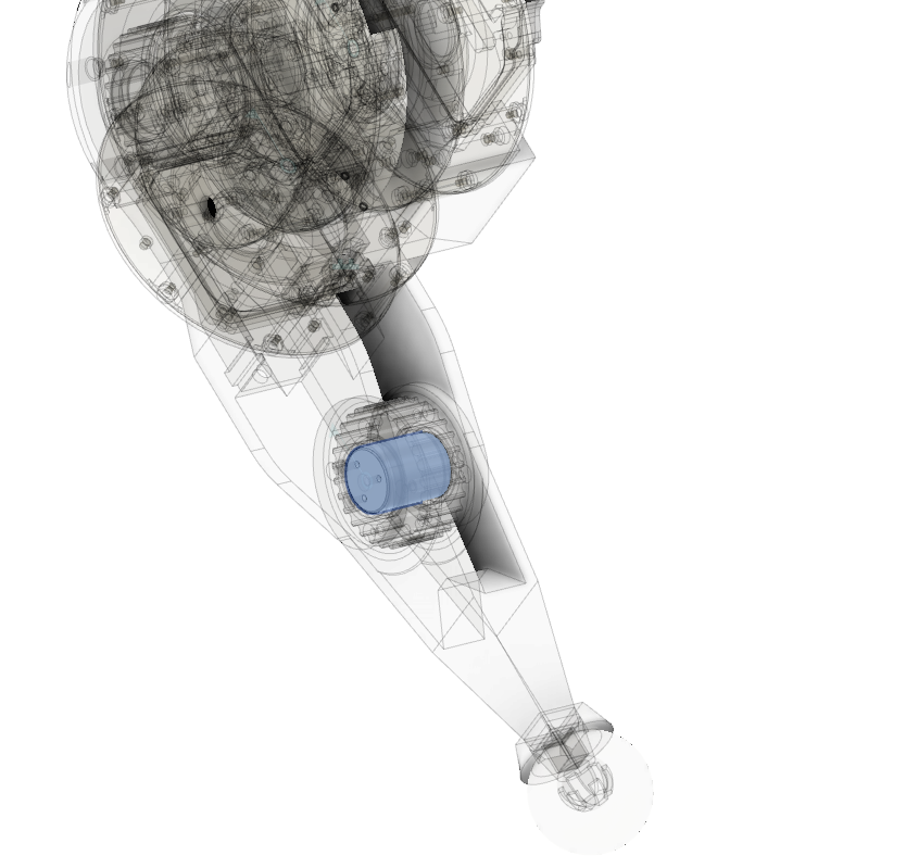
In the mk1 leg, this part was 3d printed with heat set inserts used to form the threaded holes.  This mostly worked, although occasionally the stud could shear along the 3d printed lamination lines.  Thus, for the mk2 leg, I’m making this part out of 6061.

Updated leg design for mk2 servo

Since the mk2 moteus servo has slightly different dimensions and a different mounting pattern than my original, I needed up update the full rotation leg design to handle it.  The basic concept is the same, except for some in-progress work on the foot design which I’ll write up later.  The only significant changes were that because of the mk2 design, access to the power and data connectors is much easier.

Here’s a brief CAD snapshot:

First assembled full rotation leg

As I described earlier, the first draft brushless quadruped leg design was insufficiently robust for the gearbox driven motors and I am updating it to a geometry that allows full rotation.  I’ve made at least some progress on that front, so here is an intermediate report.

First, after doing some analysis, it appeared that the 3mm pitch 6mm wide belt was unlikely to be able to carry the full torque from the motors.  So I’ve switched to a 5mm pitch 15mm wide belt, which while still unable to carry the full torque indefinitely is only a factor of 2 or 3 off instead of a factor of 20 off.  Secondly, I added a bearing opposite the upper pulley so that it is supported from both sides.  The recommended belt tension for this belt works out to something like 120lb, which is a fair amount of cantilevering, even over the 16mm wide pulley.  The updated CAD looks like:

Full rotation leg design

Another of the failure modes observed during the 2019 Maker Faire was in my quickly slapped together leg design.  The shoulder joint was required to squeeze two motors together against a strongly tensioned belt, using nothing but a relatively thin section of printed plastic.  This caused it to deform, leading to belt tooth skipping, and then eventually to fail, leading to delamination of the shoulder joint.

My plan to resolve this is to switch to a leg design where the upper and lower leg are in series rather than opposing one another.  This is more like the Mini-Cheetah design from Ben Katz.  This has the benefit of getting the leg out to the side, so the upper leg is free to rotate 360 degrees, only limited by cable harnessing.  As seems to be my pattern, I’ll try making something out of 3d printed PETG first, optimize it some, and if I fail there, switch to metal.  Here’s a render of the current CAD: