Engraving on curved surfaces with the Pocket NC v2-50
I made up a YouTube video showing the techniques I used when manufacturing the beta edition of the qdd100 servos TODO link. Check it out:
I made up a YouTube video showing the techniques I used when manufacturing the beta edition of the qdd100 servos TODO link. Check it out:
To date with my machined parts, I’ve mostly left everything in an “as-machined” state. As I get ready to make some servos where I care at least a little about how they look, I decided to invest a little in surface finish options. I started using some Scotch-Brite, which gave passable results for some components, but it was hard to be consistent and the final results were always somewhat anisotropic.
I’m planning on building up a set of mk2 servos to test them on a quadruped and make some development kits. As of now, I’ve got all the materials in house for the build and many things partially assembled!
A bunch of back housings
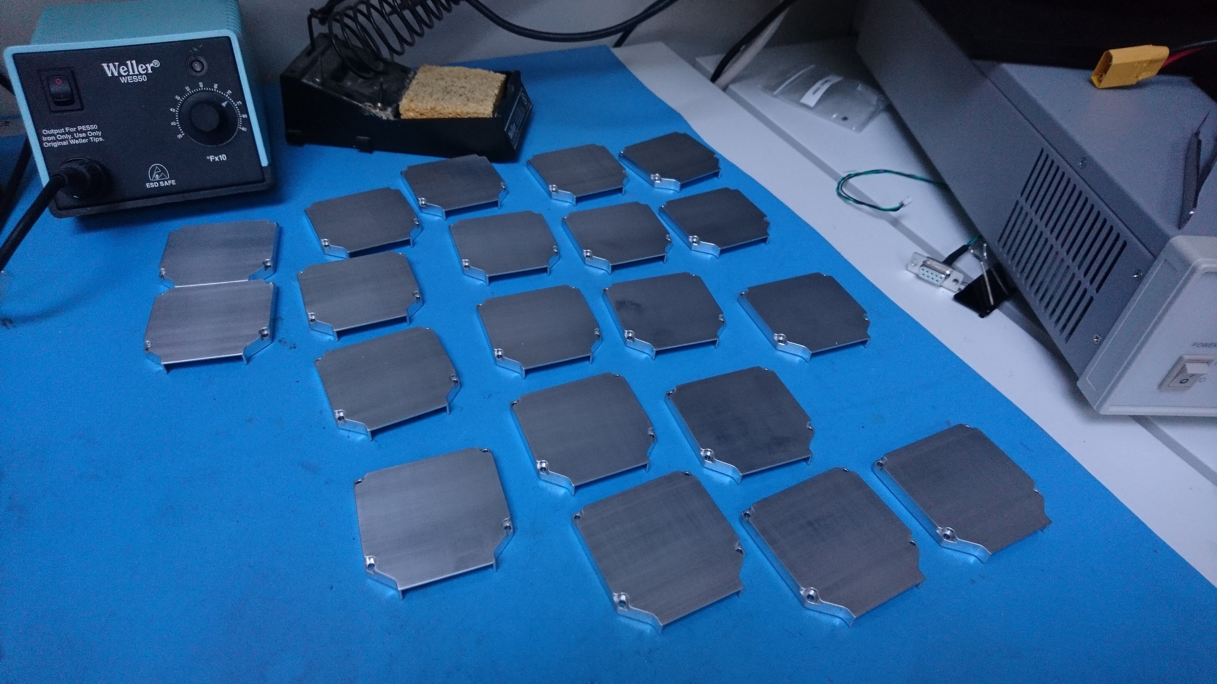
Back covers post-brushing
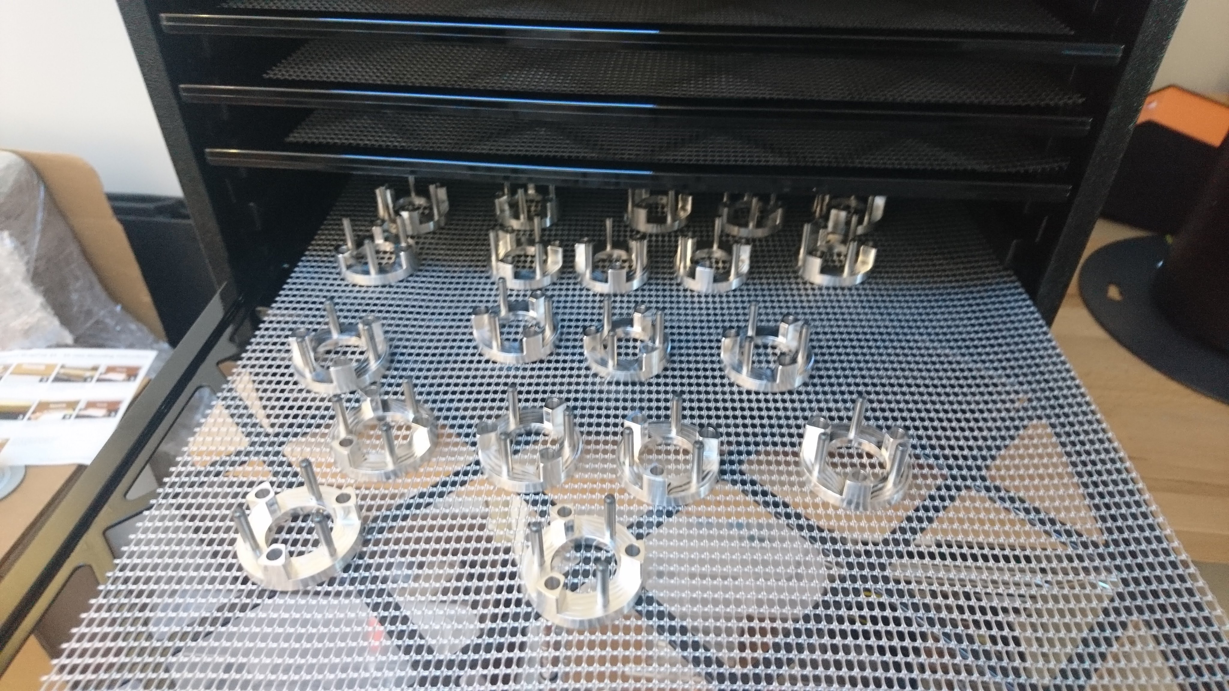
A bunch of planet inputs
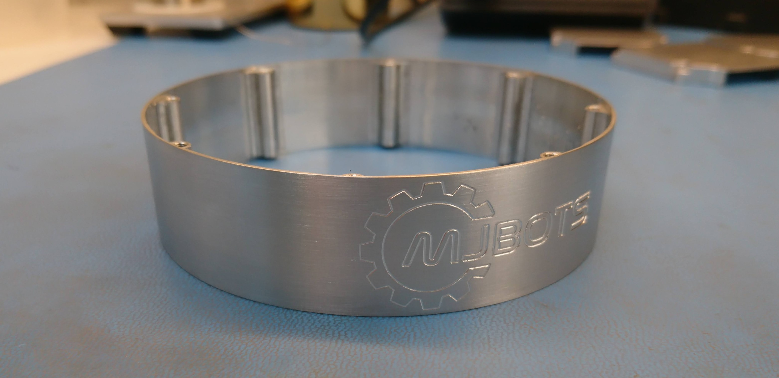
A test of the final finish of the outer housing
One of the parts on the original quad A0’s leg that was prone to failure was the “knee stud”, a little cylinder that acted as the mating interface between the upper leg and the lower leg. It directly attaches to the upper leg, and has bearings that ride between it and the lower leg. The entire tension of the leg belt is born in shear by this part.
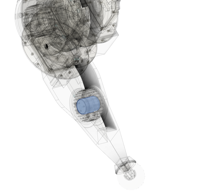
In the mk1 leg, this part was 3d printed with heat set inserts used to form the threaded holes. This mostly worked, although occasionally the stud could shear along the 3d printed lamination lines. Thus, for the mk2 leg, I’m making this part out of 6061.
Just because I’m generally looking for workholding solutions for the Pocket NC, I recently picked up a vise designed for it from wcubed.co.
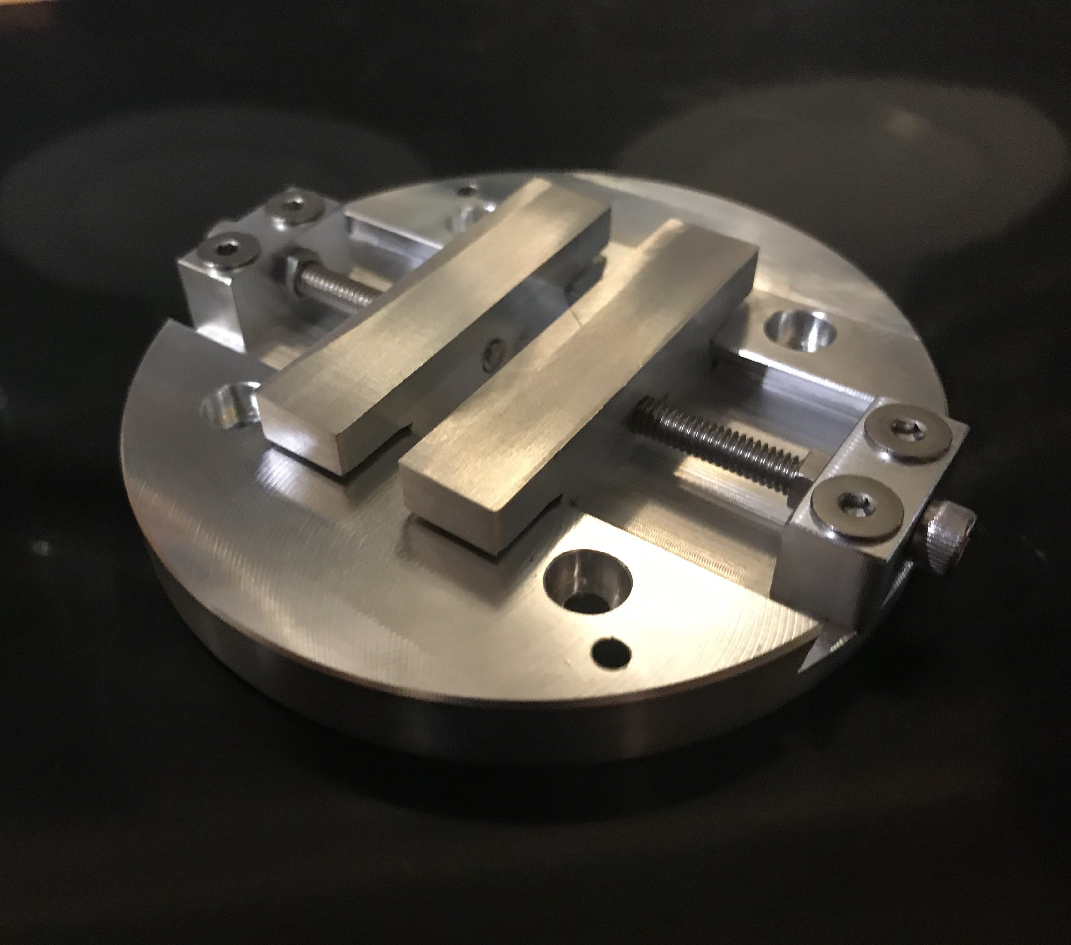
Unlike the stock vise that comes with the PNC, this has two movable aluminum jaws. It can probably hold with greater force than the stock vise, since there is a larger contact area, although the screw mechanism doesn’t necessarily apply the force all that uniformly. Also, since both jaws are movable, you have to take some care to either manually center things, or do some edgefinding, which isn’t terribly easy on a PNC.
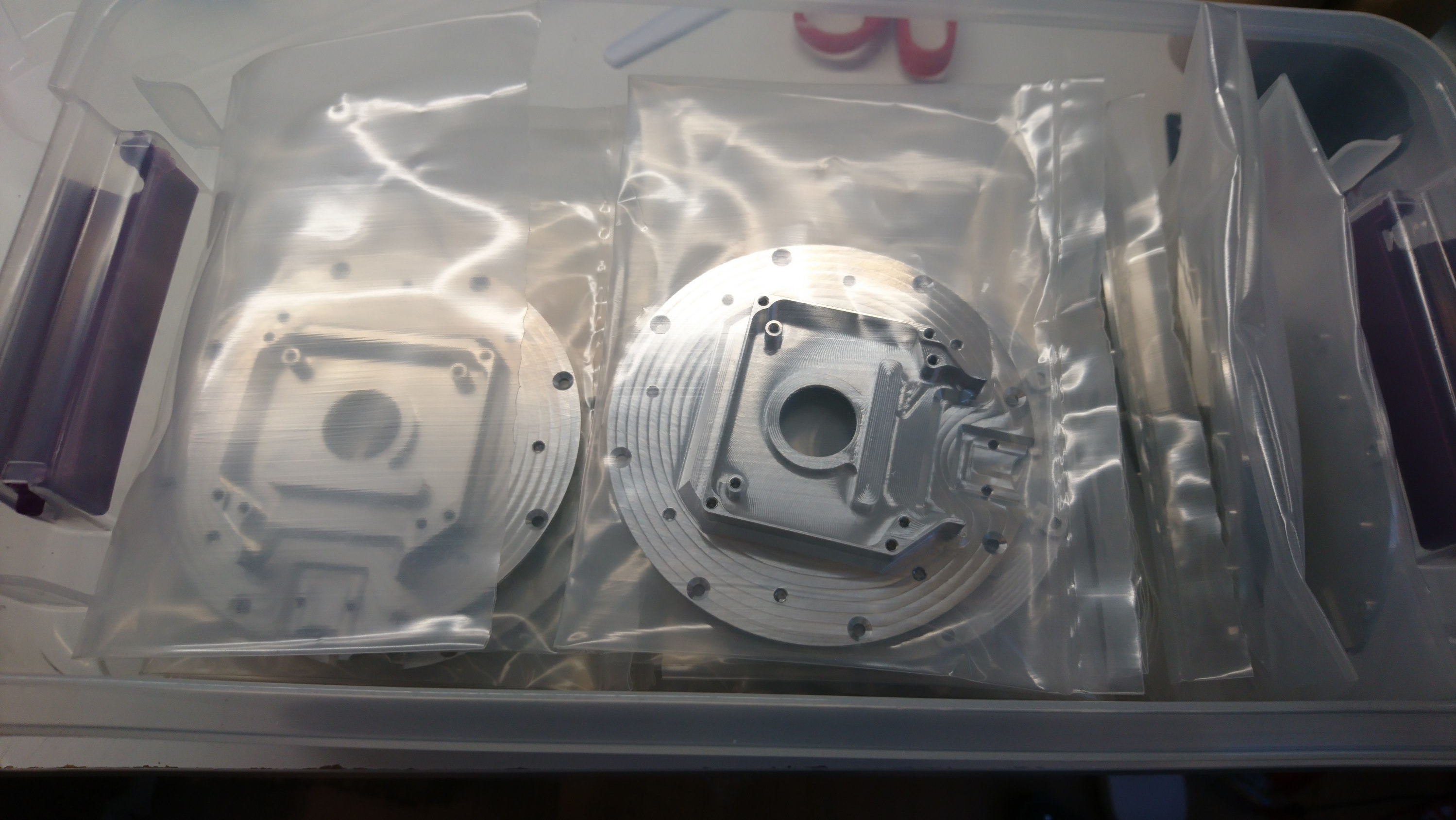
As mentioned previously, I made up some soft jaws to hold 4in round stock in a 6" vise. My goal was to prepare stock for workholding on the Pocket NC v2-50 to machine prototypes of the front and back housing for the reduced weight moteus servo mk2.
Now, I’ve used those soft jaws to trim down both pieces of stock to the correct length, bore a center hole, and in the case of the front housing, remove a bunch of additional material in a more expeditious manner. There’s not much more to it than that, so here’s the video:
While working to build the reduced weight moteus servo mk2, I got tired of hand machining the first operation on a manual mill and lathe for the front and back housings. It was necessary, primarily to enable workholding on the PocketNC v2-50, but also because it allowed me to remove much of the excess material more quickly than could be done on the PNC. So, I got trained up on the AA CNC Bridgeport and went to town.
While working to build a weight reduced moteus servo mk2, I reworked my outer housing CAM to do all the machining on the Pocket NC v2-50. For this part I didn’t necessarily need any challenging workholding and since I could get the stock in tube form, there wasn’t an inordinate amount of material to remove either.
The one challenge is that when mounted in the Sherline Chuck, the mill can’t actually reach all the way to the edge of the part without hitting the X travel limit (which is why most of the other 100mm diameter parts I do are fixtured slightly off-center). In this case I tackled the problem in two iterations.
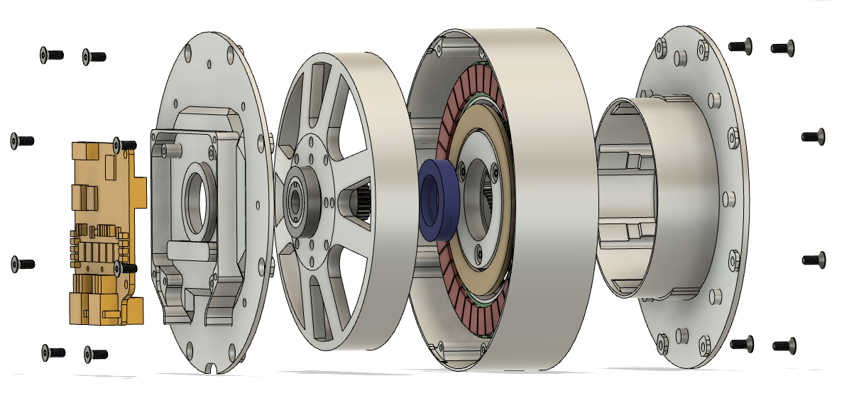
After having produced the first functional demonstration of the moteus servo mk2, my next step was to decrease the weight. While I was at it, I made two other changes:
After machining a fair number of parts with threads, I’ve tweaked my thread milling feeds and speeds to both go a little bit faster, give a more reasonable fit, and remove the last bit of niggling interference with the M2.5 recipe.
I’ll list the changes here, and have updated the original recipe
| Old | New | |
|---|---|---|
| Chamfer Width | 0.10mm | 0.05mm |
| M3 Pitch Diameter Offset | 0.538mm | 0.568mm |
| M3 Stepovers | 10 | 6 |
| M3 Repeat Passes | NO | YES |
| M3 Lead To Center | NO | YES |
| M2.5 Pitch Diameter Offset | 0.430mm | 0.480mm |
| M2.5 Stock to Leave | 0.0mm | -0.02mm |
| M2.5 Stepovers | 7 | 4 |
| M2.5 Repeat Passes | NO | YES |
| M2.5 Lead To Center | NO | YES |
Notably, the “Lead To Center” option found on the linking tab is what prevents the M2.5 threads from rubbing when inserting in later passes. Thanks to Quincy Jones from Implemented Robotics for that tip over in the mjbots discord!