New quad raspberry pi interface board
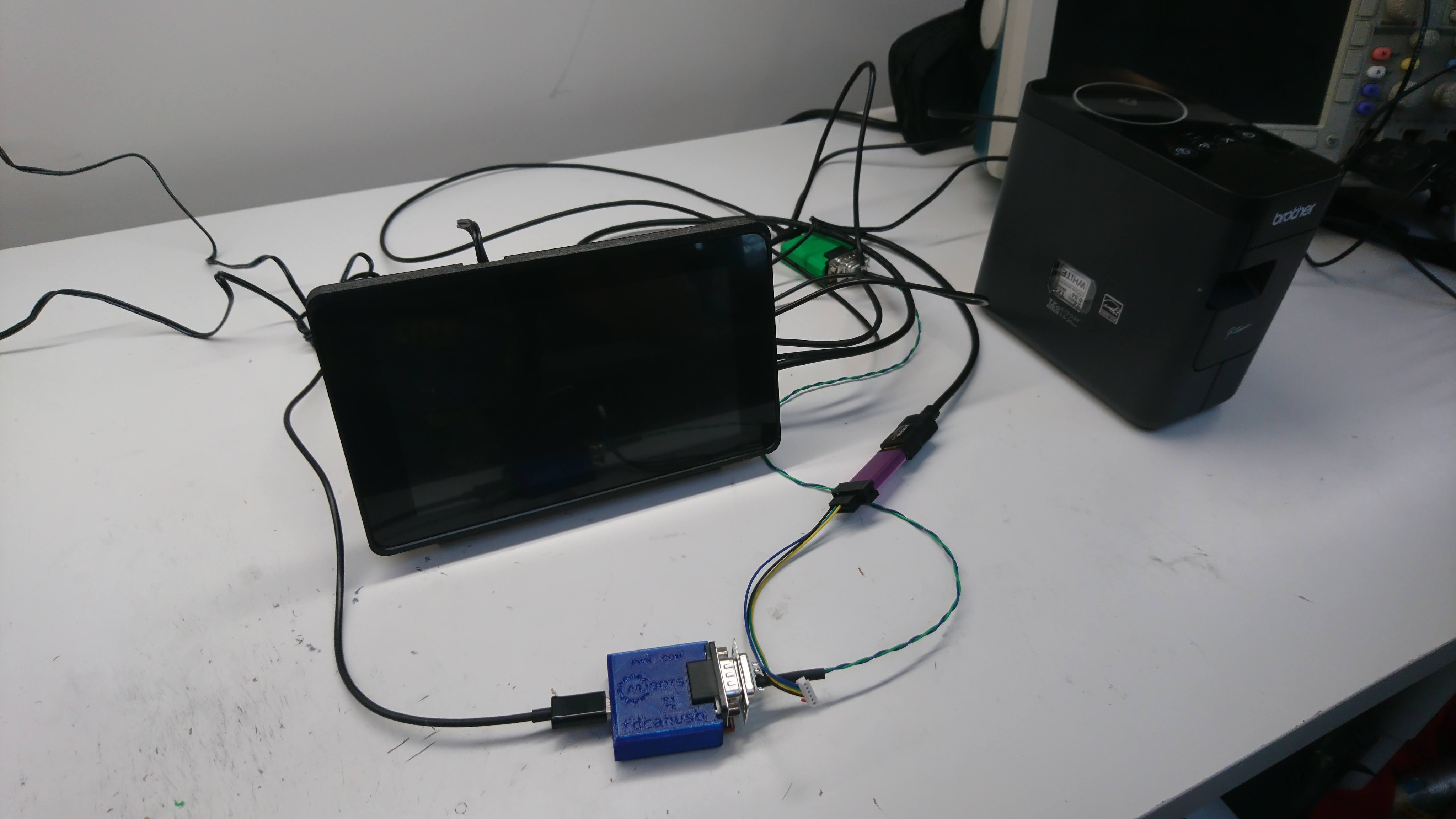
With the new FD-CAN based moteus controllers I need a way for the raspberry pi to communicate with them. Thus I’ve got a new adapter board in house that I’m bringing up:
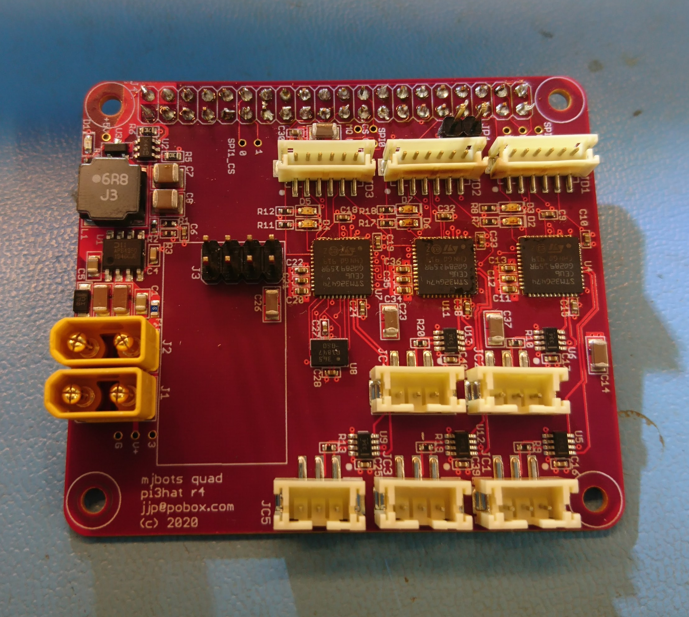
This one has 5 independent FD-CAN channels, an IMU, a port for an nrf2401l RF transceiver as well as a buck converter to power the computer from the main battery bus.
The prototypes were largely constructed by MacroFab, although I did the Amass connectors and the STM32s because supply chain issues prevented me from getting those parts to MacroFab in time.