Continued moteus r4.1 bringup
While continuing to bring up the r4.1 moteus controller I reached a mini-milestone where it spun a motor for the first time!
While continuing to bring up the r4.1 moteus controller I reached a mini-milestone where it spun a motor for the first time!
After having produced the first functional demonstration of the moteus servo mk2, my next step was to decrease the weight. While I was at it, I made two other changes:
Another step in my plan for the next revision of the moteus servo mk2, is an updated controller board. As mentioned in my roadmap, I wanted to revise this board to make improvements in a number of domains:
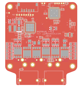
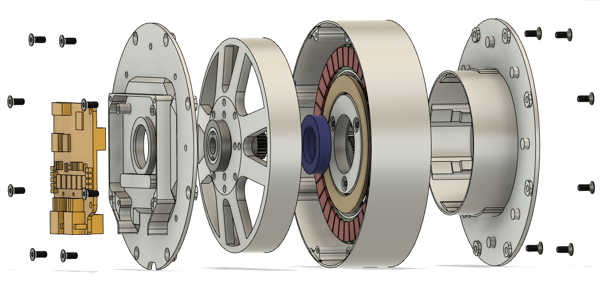
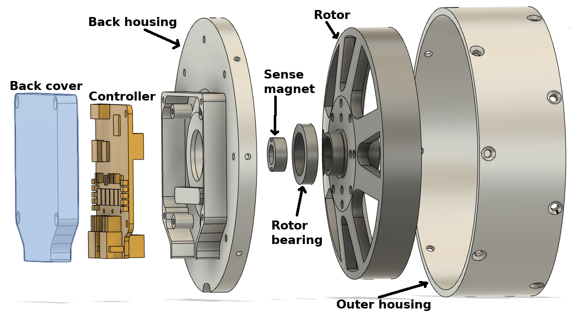
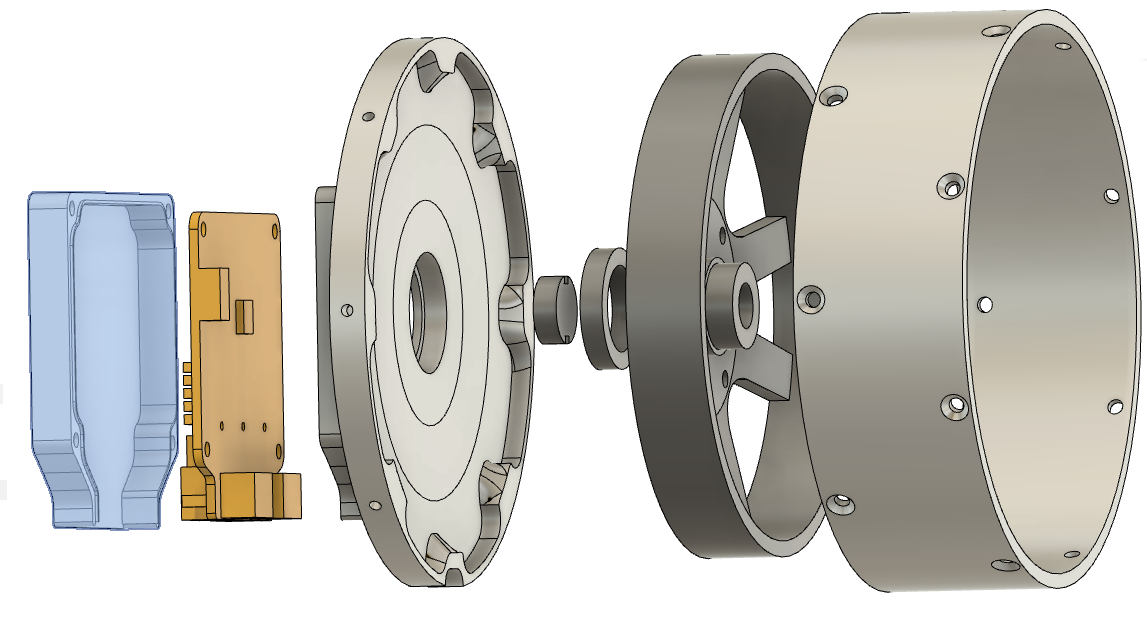
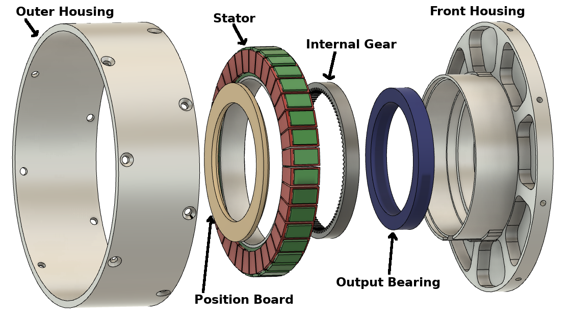
moteus r4.1 rendering
After machining a fair number of parts with threads, I’ve tweaked my thread milling feeds and speeds to both go a little bit faster, give a more reasonable fit, and remove the last bit of niggling interference with the M2.5 recipe.
I’ll list the changes here, and have updated the original recipe
| Old | New | |
|---|---|---|
| Chamfer Width | 0.10mm | 0.05mm |
| M3 Pitch Diameter Offset | 0.538mm | 0.568mm |
| M3 Stepovers | 10 | 6 |
| M3 Repeat Passes | NO | YES |
| M3 Lead To Center | NO | YES |
| M2.5 Pitch Diameter Offset | 0.430mm | 0.480mm |
| M2.5 Stock to Leave | 0.0mm | -0.02mm |
| M2.5 Stepovers | 7 | 4 |
| M2.5 Repeat Passes | NO | YES |
| M2.5 Lead To Center | NO | YES |
Notably, the “Lead To Center” option found on the linking tab is what prevents the M2.5 threads from rubbing when inserting in later passes. Thanks to Quincy Jones from Implemented Robotics for that tip over in the mjbots discord!
Now that I have at least one functioning version of each of the pieces made for the moteus servo mk2 (planet input, outer housing, front housing, and back housing), I integrated all of them together into a functional prototype.
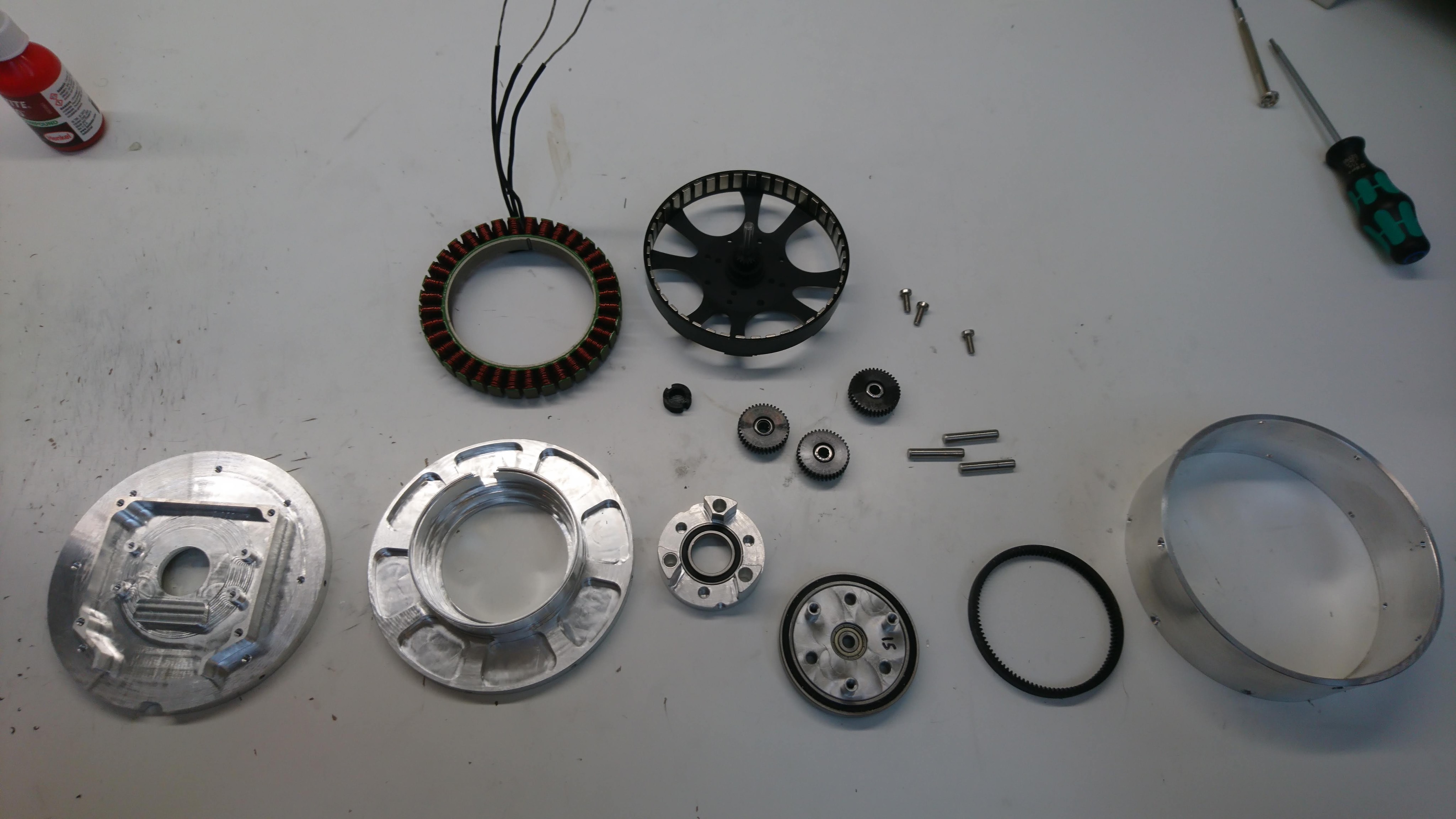
A bunch of pieces
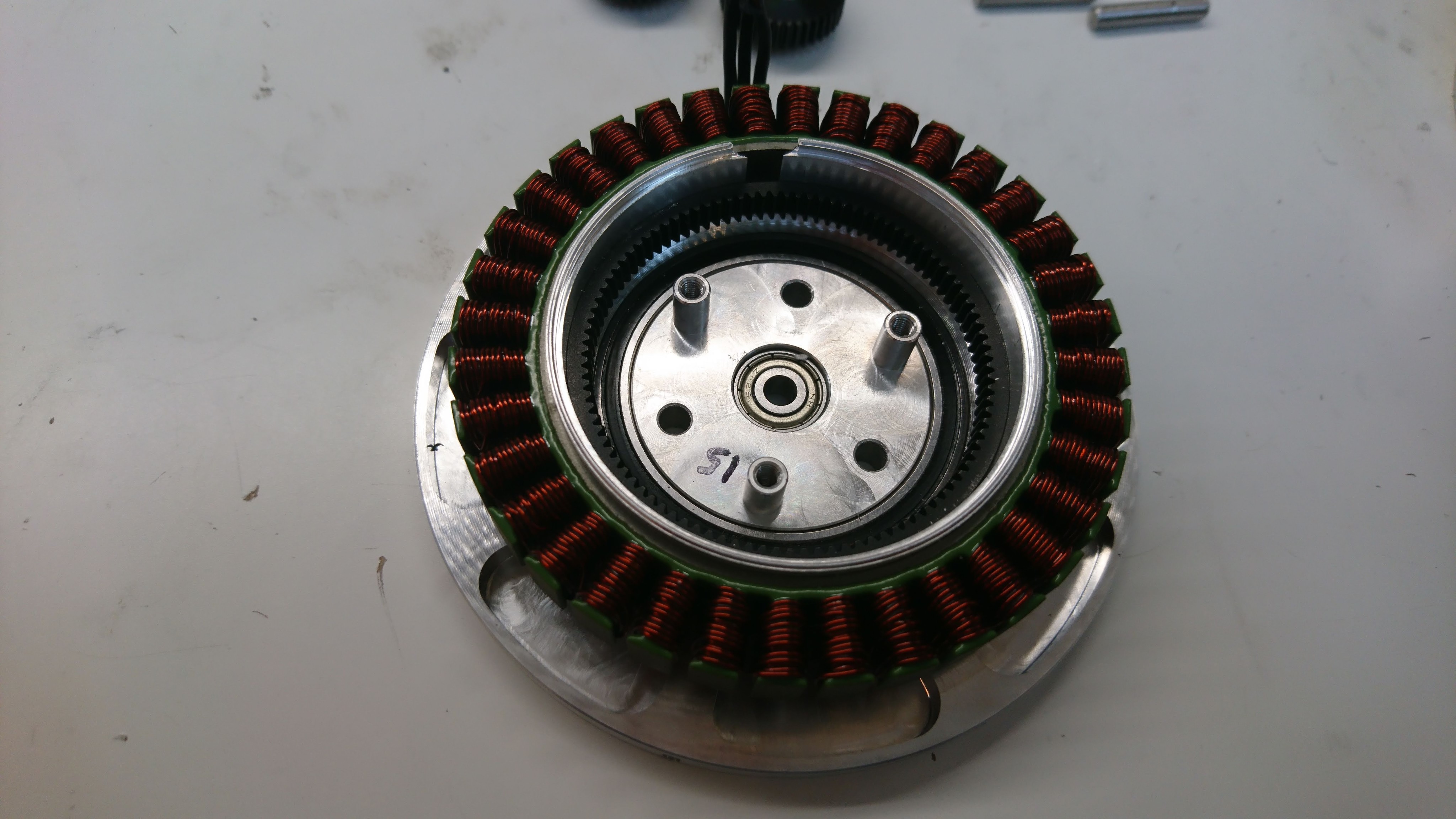
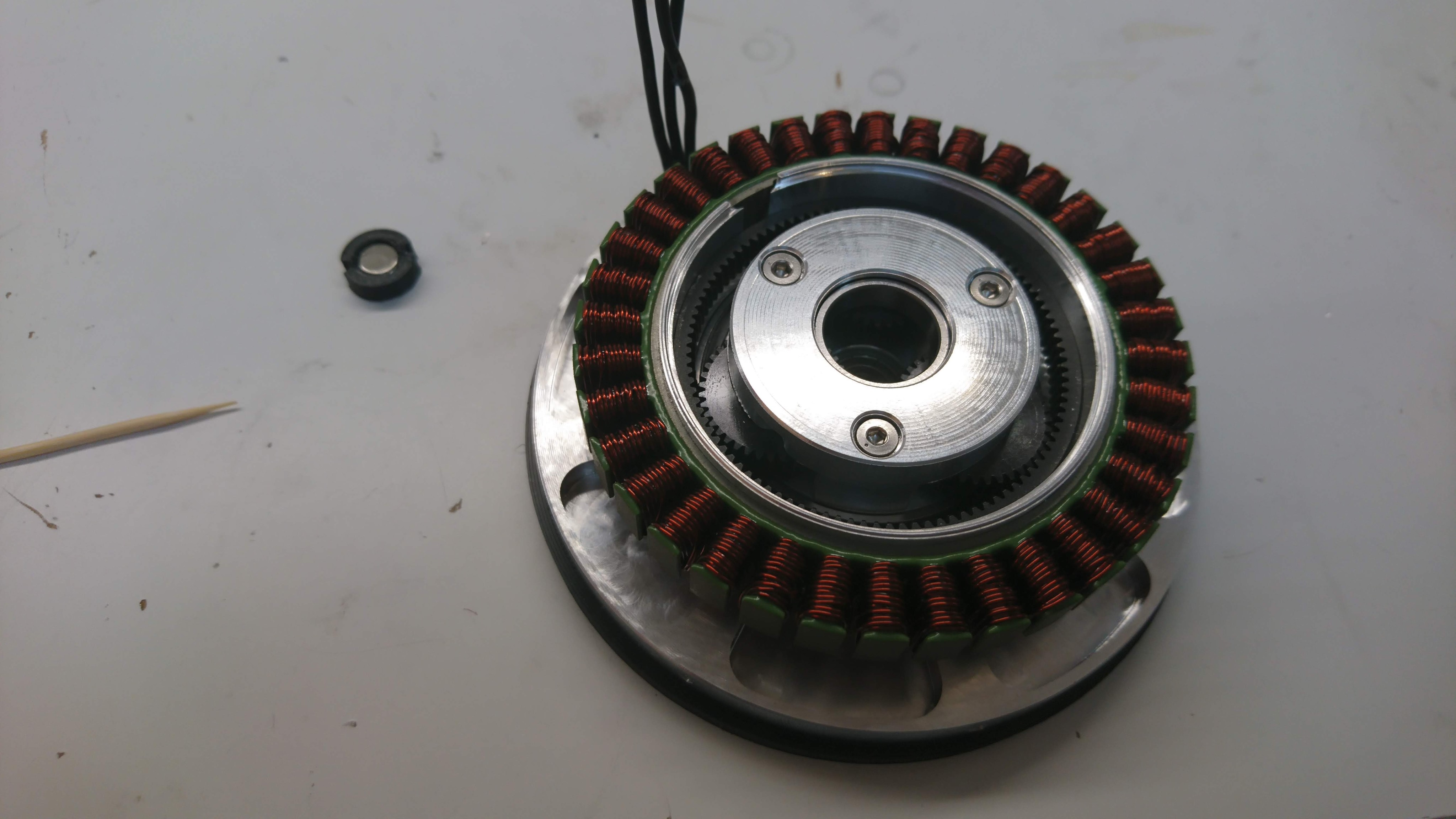
Front housing with stator, internal gear, and planet output installed
Planet input, gears, and shafts installed
The back housing is the final piece of the moteus mk2 servo that I wanted to prototype. (The planet output is identical to the mk1, so I could use extra stock I had of it for the prototypes). It is large, and only mates directly to 4 other things, which makes it a little less complex than the front housing.
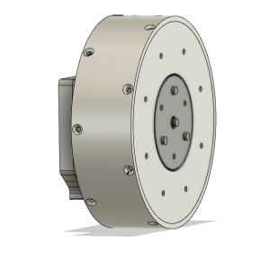
I had initially designed the back housing to mate to the as-yet-unannounced new version of the moteus controller, the r4.x series. Unfortunately, I don’t have any of those working yet, so I tweaked the design to temporarily fit a r3.1 controller, which looks like this:
The front housing is the most complex machined piece in the moteus servo mk2, as it was in the mk1. It is relatively large and mates with many other components with the associated tight tolerance surfaces. For mk2, the front housing is even larger in diameter, but otherwise has the same basic features.
Building a prototype of this was a real challenge given the tools I have available to me now. For mk1, I didn’t even try and just had Xometry build my prototypes, and was lucky enough that the first ones worked. My only CNC currently is the Pocket NC v2-50, which is just barely big enough to deal with this part, and has no convenient workholding that can be used for the stock. Also, it has a low material removal rate, such that starting from stock here would be prohibitively time consuming.
The outer housing for the moteus servo mk2 is just a precision round tube with some mounting holes drilled peripherally. Still, manufacturing it was slightly annoying, mostly because of my available machining resources.
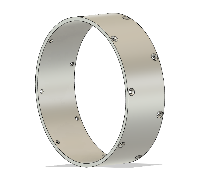
I started off with round tube stock with some extra margin on the inside and outside:
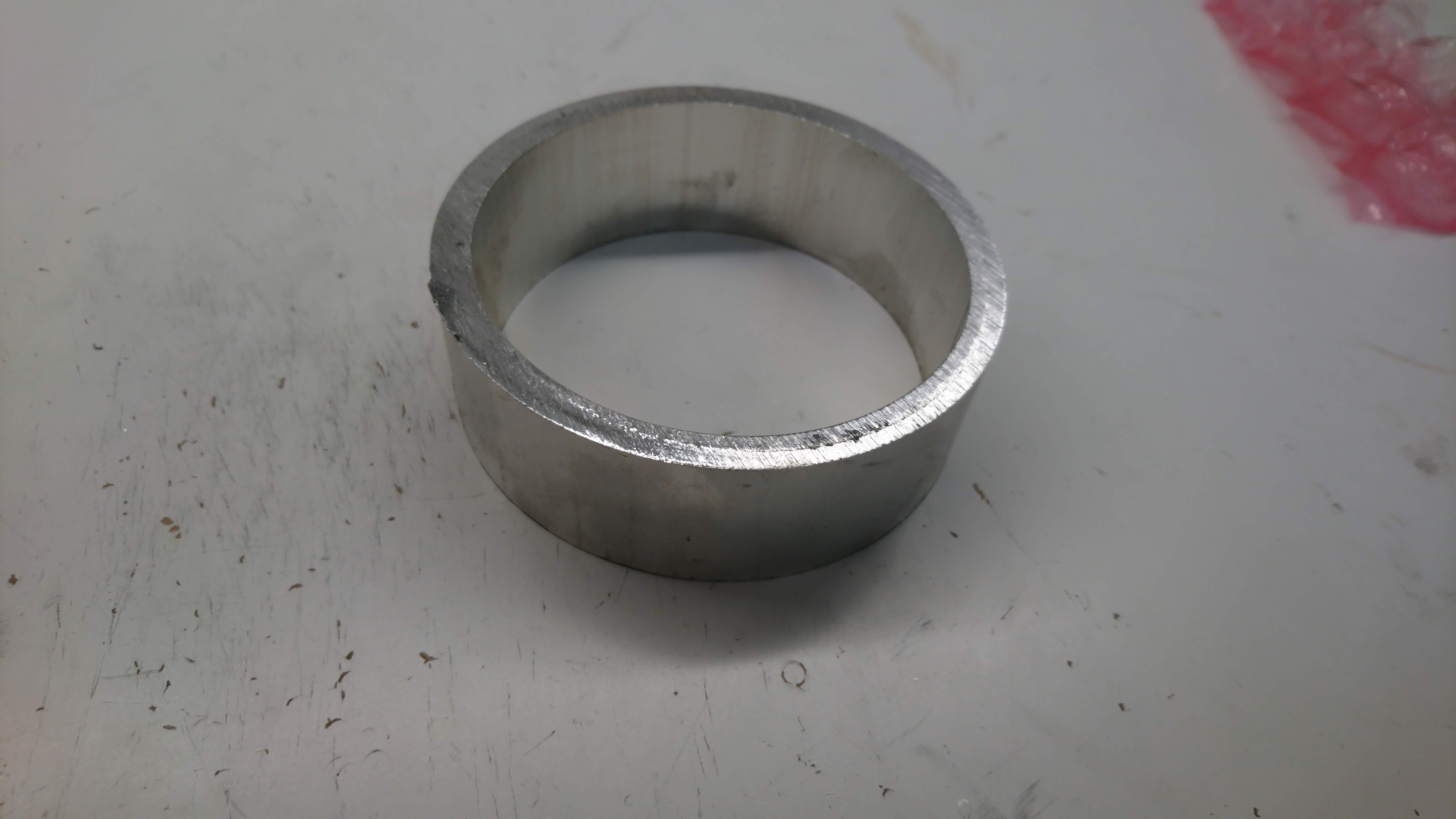
Then I went and used the manual lathe at Artisan’s Asylum to get the correct ID, OD and length:
As the first part of the new moteus servo mk2, and continuing in my series of learning about CNC by building parts for the quadruped, next up I machined the input to the planet gears on my Pocket NC V2-50. This was a part, that for my quad A0 build, I used a 3d printed part in PETG as it is probably the least stringent part in the gearbox in terms of tolerances and load, although I still expect the plastic ones will likely wear and fail after some time with heavy use.
As described in my roadmap, making a new revision of the moteus servo is up there on my list of things to do. The initial servos were a work of art, yes, but also pretty fragile, very labor intensive, and still not all that robust. My goals this time around are:
CAD rendering