Archives: Development

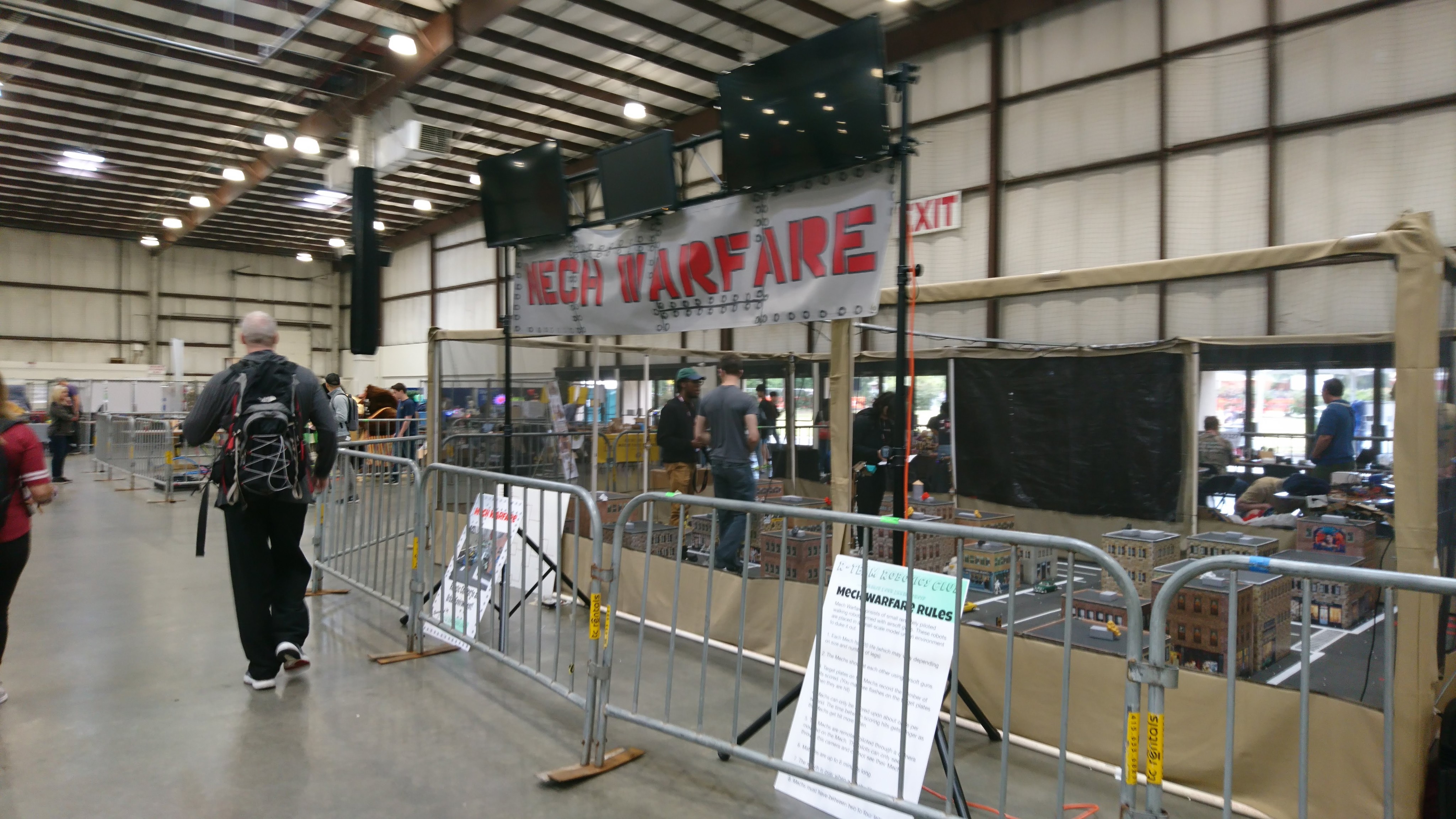
Mech Warfare 2019 - First look

Well, Mech Warfare at Maker Faire 2019 has come and gone.  Maker Faire was a really awe inspiring event, and RTeam did an excellent job organizing the Mech Warfare competition.  There were something like 13 teams with moderately functioning mechs who competed across the 3 days.

dsc_0037

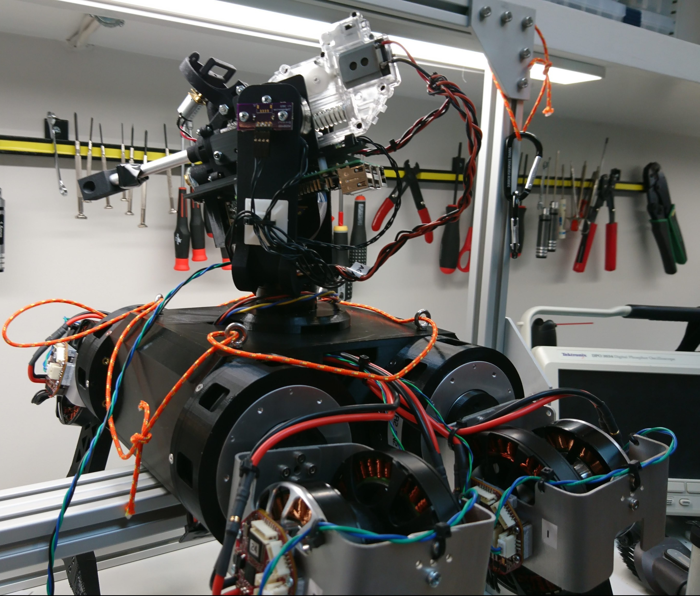
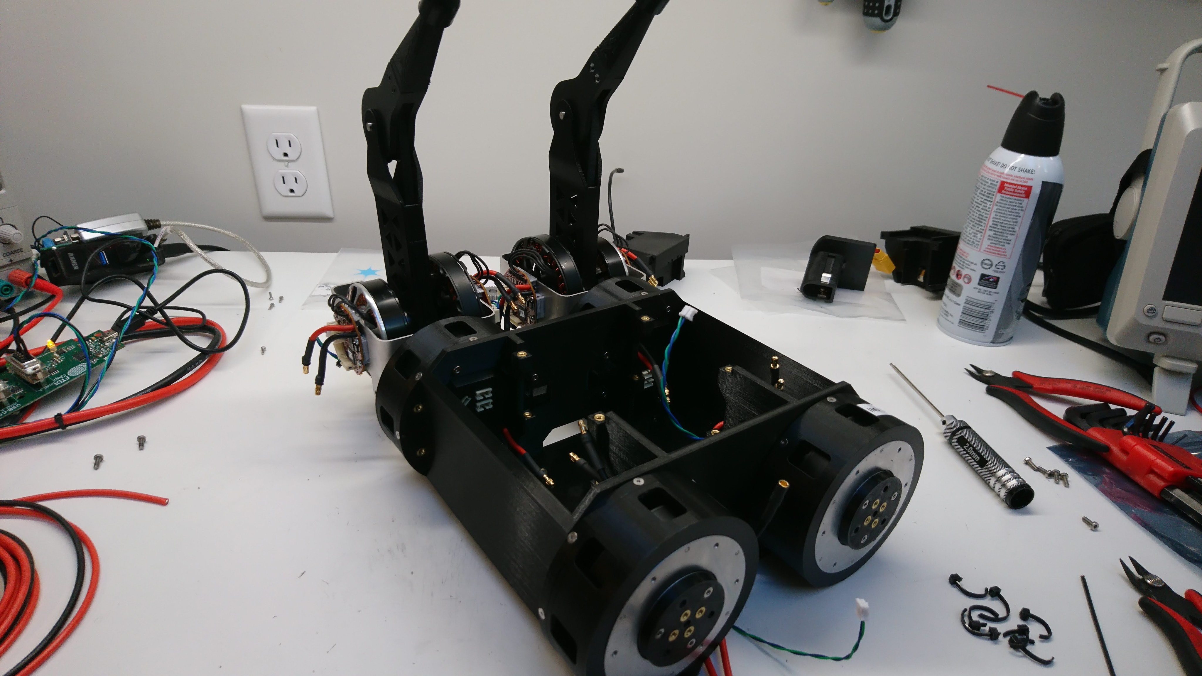
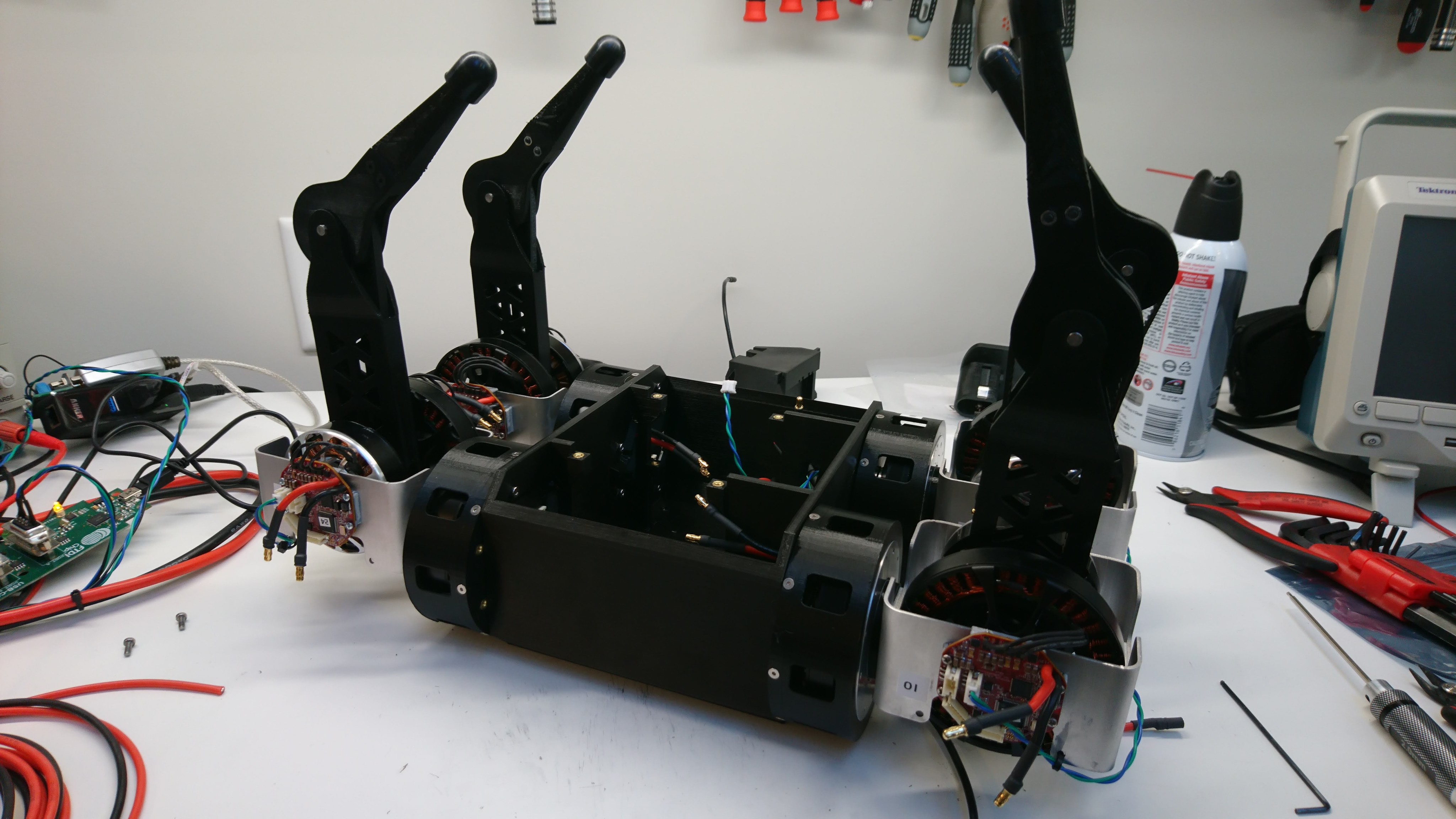
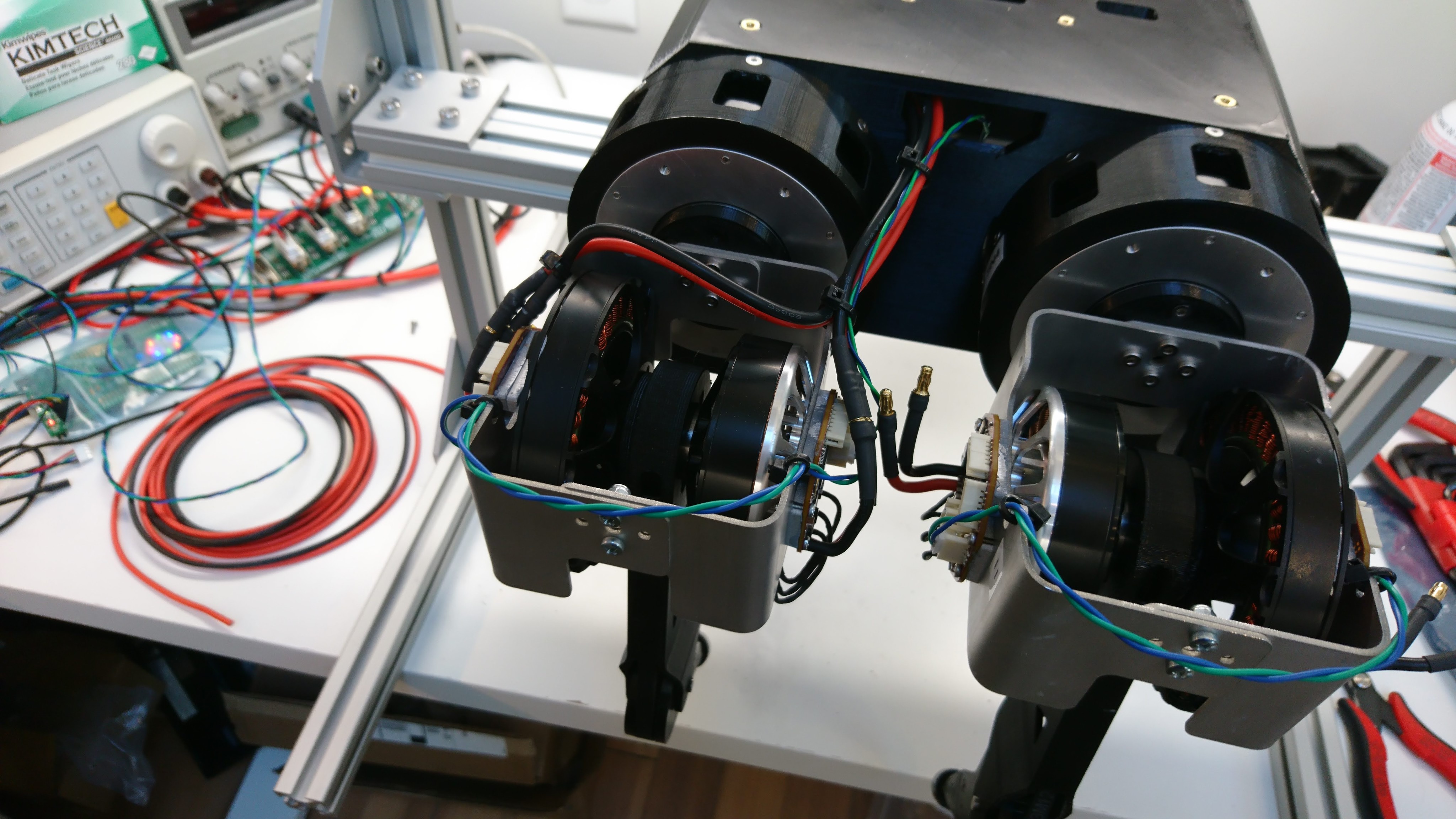
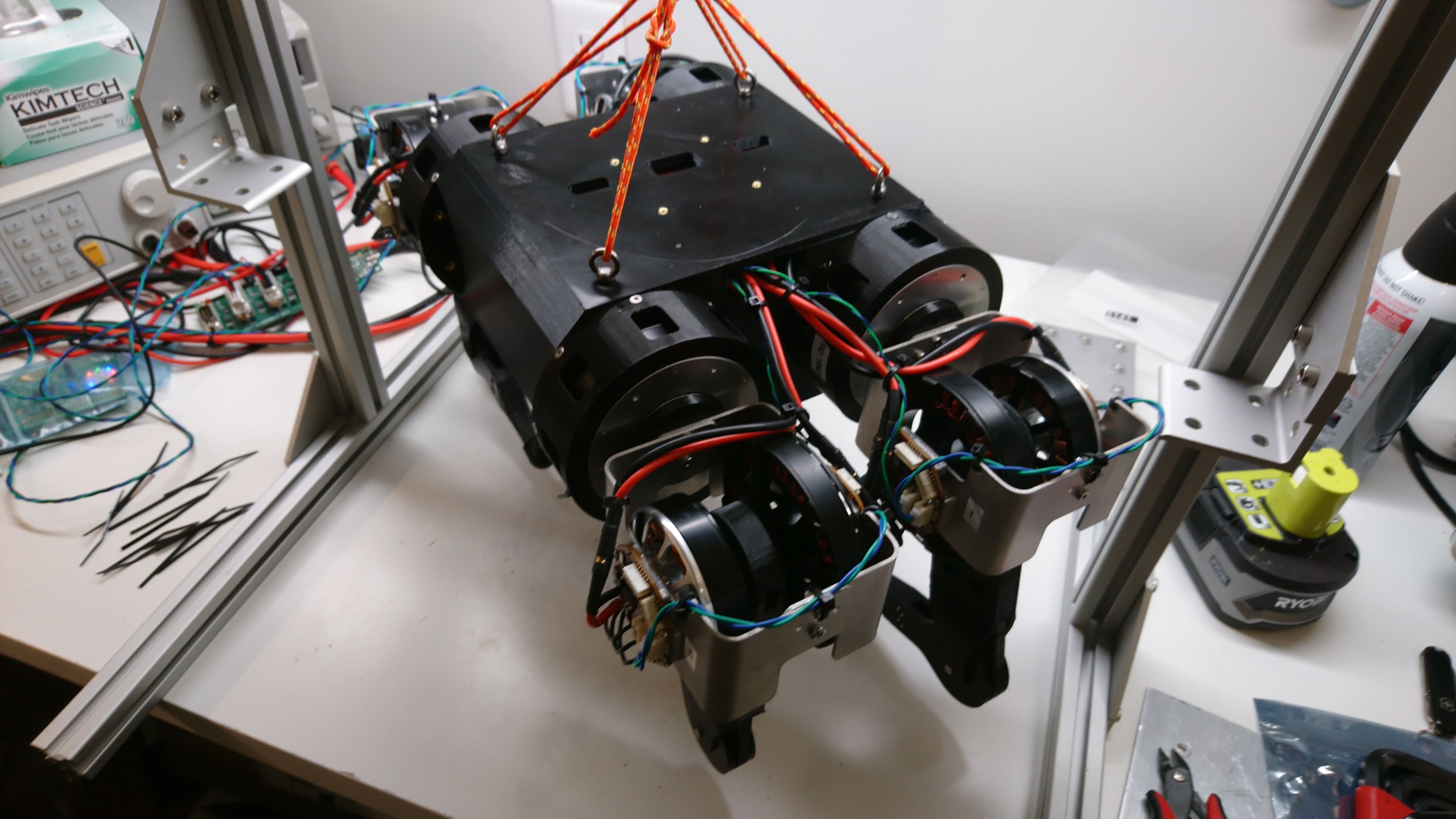
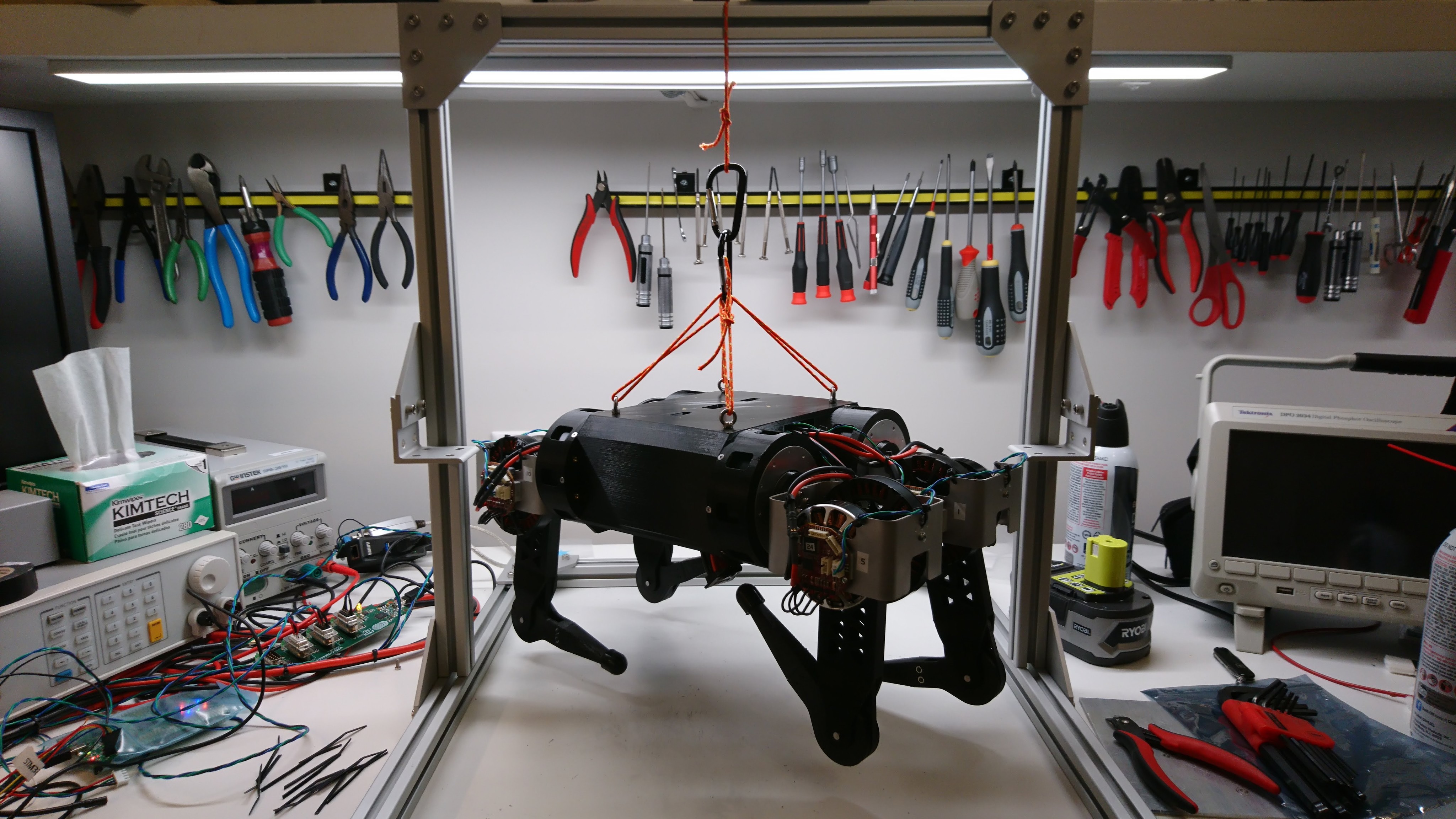
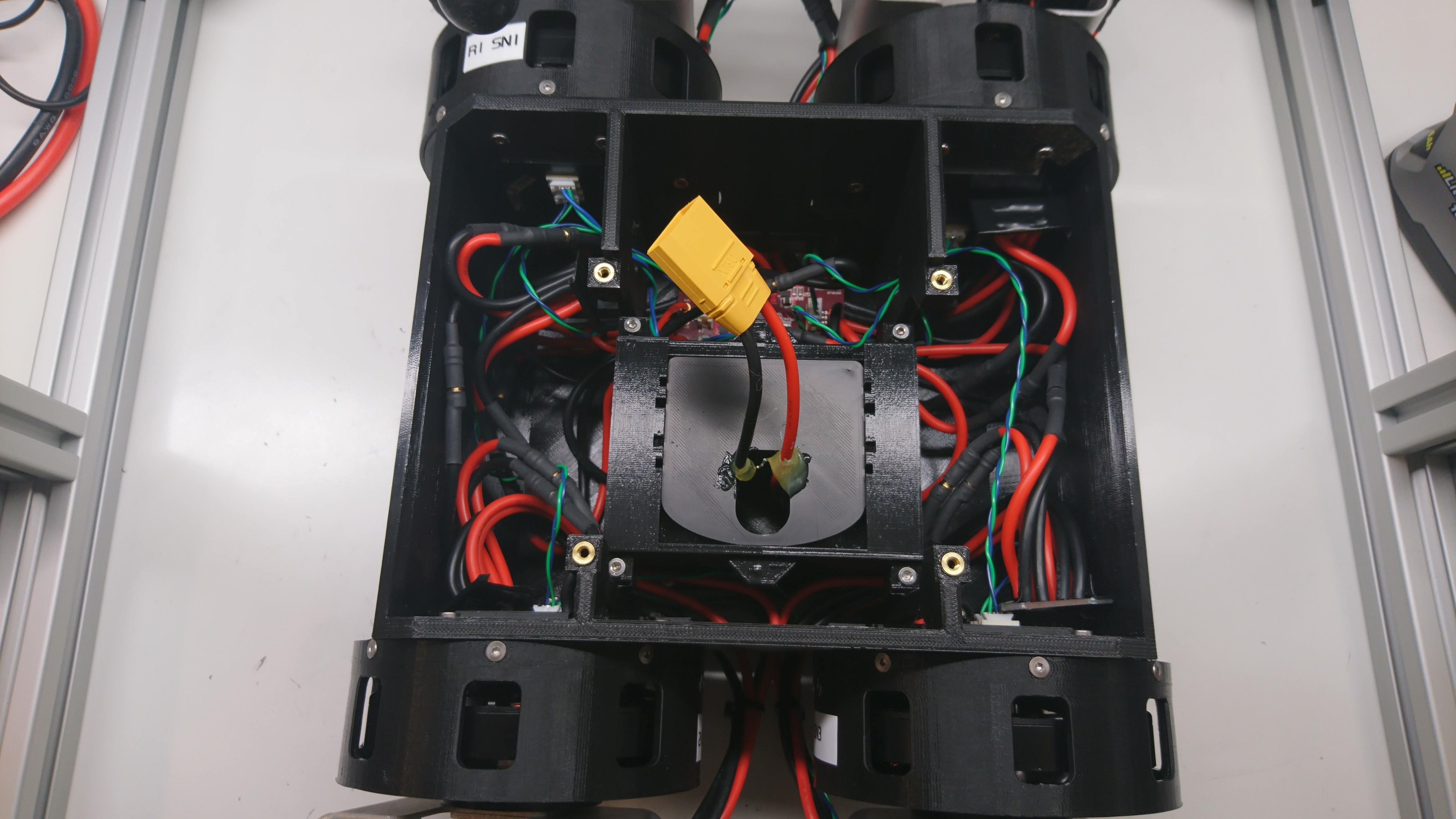
Super Mega Microbot “Junior”

My entry, Super Mega Microbot Junior, did manage to walk a bit in 3 matches, but had a previously unseen failure in the turret system that rendered it inoperable a short while into each match.  At the end of the 3rd match, one of the leg joints sheared off, and some other of the 3D printed parts were about to fail as well, so I declared it unrepairable at that point.

The gearbox sprint

As mentioned last time, I needed to build a lot of gearboxes and new leg assemblies in a very short amount of time. So, I got to work.

Machining operations

I made a new fixture for holding stators to be extracted:

Stock in the vise

Stock in the vise

Countersinks milled

Countersinks milled

Stator mounted and fractionally machined

Stator mounted and fractionally machined

I turned down 8 more internal gears. To begin with, my mandrel had warped enough from the first gears that I had to add some heat set inserts to hold a cap to keep the gears on. Then on the last 2 gears, I got greedy, went too fast, and my lathe mandrel melted entirely.

Making things walk - and failing

Now that I could stand up and sit down, I needed to be able to walk reliably for the length of a match.  This wasn’t going to be easy because the direct drive motors were always a bit marginal in their power output to support the full robot, so I had my work cut out for me.

The short story is, I tried many things, spent about a day examining high speed video of walking, and made some improvements:

Standing up and sitting down

Before SMMB could function in the Mech Warfare event it needed to be able to start and stop unattended.  That meant standing up and sitting down on its own.  Being that hack that this was, I went for a two pronged approach.

The direct direct servos I have for the upper and lower legs are somewhat underpowered for this size of robot.  Especially so when the machine is fully squatting down.  Also, the servos aren’t really encapsulated at all, and there are plenty of leg configurations that can self-intersect resulting in robot harm.

pre-charge circuit

Next up in Super Mega Microbot 2’s existence is being able to run untethered.  Before that can happen, I need to be able to plug in a battery, and hopefully not have everything explode.  As seen with the IMU junction board, even minor inductive links can result in chips getting toasted.  I had thought that just adding sufficient capacitance to each of the point-of-load converters would resolve the issue, but in fact that almost made it worse.

Connecting up the turret

With the turret functioning in isolation, now I needed to mount it on the robot and get things communicating.

Mounting was easy, I 3d printed a bracket that fits the turret on one side, and mounts to the 4 hard mounts on the top of the gearbox chassis.

Turret mounted on chassis

Turret mounted on chassis

More time consuming was updating the control software to communicate with it.  The old turret used the HerkuleX protocol, and when I integrated the moteus RS485 based servos, I took a few shortcuts that I knew would need to be resolved later.  And the future is now!

gimbal control board revision

With the new gearbox based mech chassis for Super Mega Microbot 2, the old gimbal controller would need some updates.  It has these new features/capabilities:

  • Higher input voltage: The old system ran at 2S, so 7.2V nominal.  Now we’re running at 5S, so 18.5V nominal.
  • RS485 data: The HerkuleX based robot used TTL level data communications.  moteus uses RS485.
  • Daisy chained power: With the new raspberry pi based computer in the turret, I now need to have an additional power and data port up on the mobile part of the turret.
  • No camera passthrough: Similarly, since the camera is directly attached to the raspberry pi 3, I don’t need to mess with having a connector to pass it through anymore.
PCB rendering

PCB rendering

rpi3 interface board

Now that I have a chassis that can walk a little bit, I need to get the onboard computer working.  To do that, I needed to update the raspberry pi 3 daughterboard I built for the previous turret for the new bus voltage and communication format.

The rpi3’s UART is incapable of controlling the direction line on the RS485 transceiver, so I added a small STM32 micro in line to control the transmit / receive direction.  It adds a little bit of latency, but testing the firmware I was able to get it down to only a byte’s worth or so.

First walking with gearbox chassis

Short recap: After building the quadruped with near-direct drive motors, I discovered that the lateral servos had insufficient position control authority to keep the robot standing up.  Thus I embarked on a now month long quest to design and build an integrated planetary gearbox.  At this point, I have enough gearboxes built for all the lateral servos, so it should be able to walk, right?

And tada!  It can!  Well, at least a little bit.  I’ve only spent a short while with the gearbox based chassis, and have a lot of work left to do.  However, here’s a quick video showing it walking around, slipping on a ruler, and almost falling over a few times.

Wiring up the gearbox chassis

Now that I had a set of 4 at least minimally working lateral servos, I needed to wire up the chassis so that everything had power and data.  Here are some pictures of that process:

Two legs installed

Two legs installed

Four legs installed

Four legs installed

Joint cable routing

Joint cable routing

Times four

Times four

Suspended from the test fixture

Suspended from the test fixture

Four sets of busbars, the junction board, and a shore power battery simulator

Four sets of busbars, the junction board, and a shore power battery simulator