Bringing up the fdcanusb
I introduced the fdcanusb previously, now I’ll describe some of the process and challenges in getting it to work.
Hardware
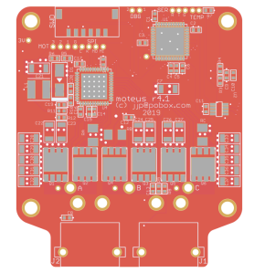
My initial challenges were around the PCB design and manufacturing. To begin with, my very first revision was sent out for manufacturing with the same incorrect pinout as the moteus controller r4.0 and thus was only really usable as a paperweight. Second, the supply of STM32G474 chips seems to be spotty now, so for r2 I had to scavenge chips from the boards that had broken pinouts.