Archives: Development

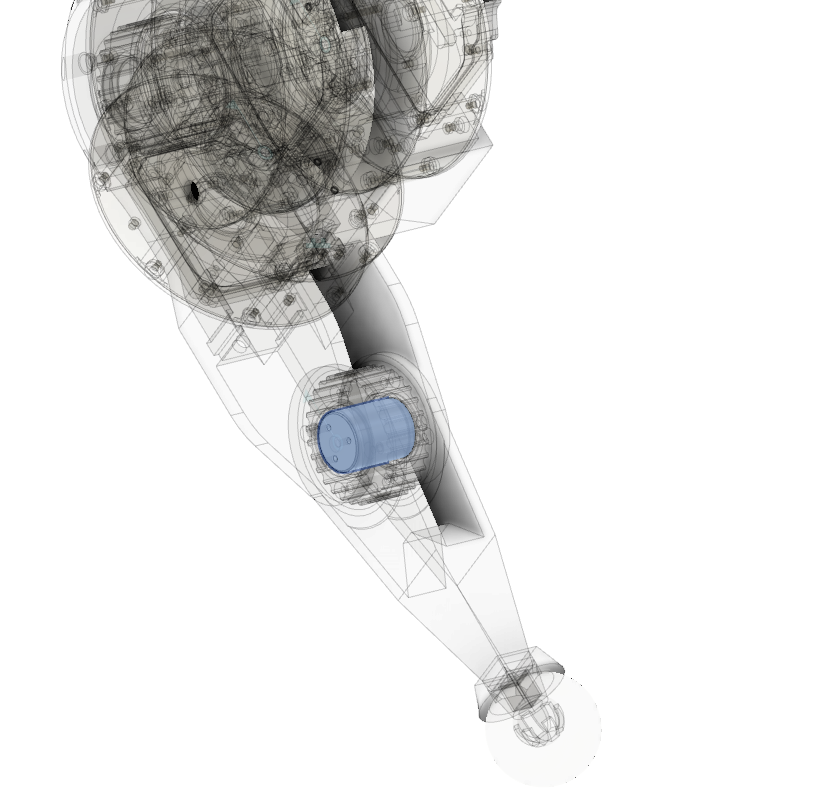
mk2 leg knee stud

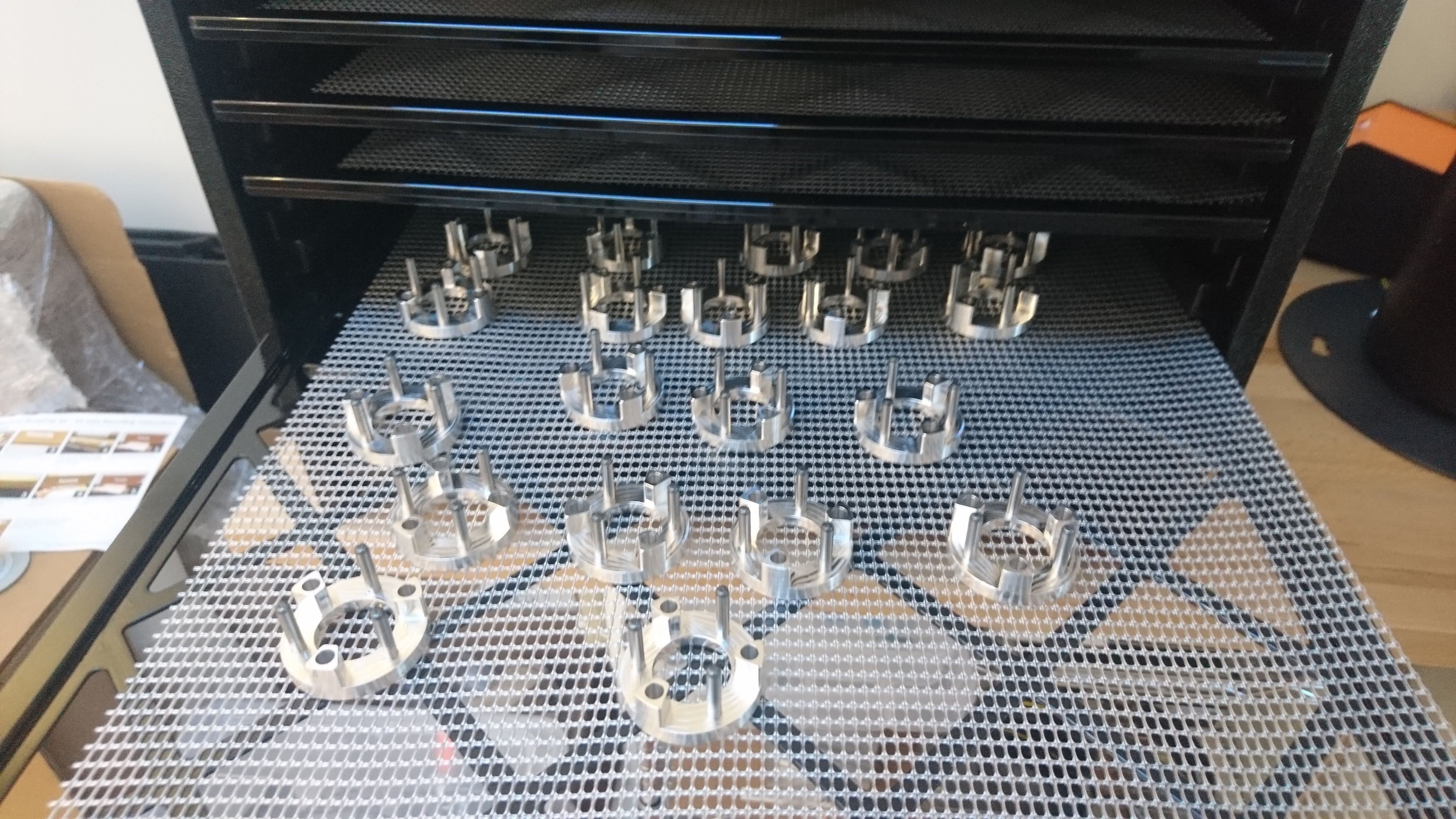
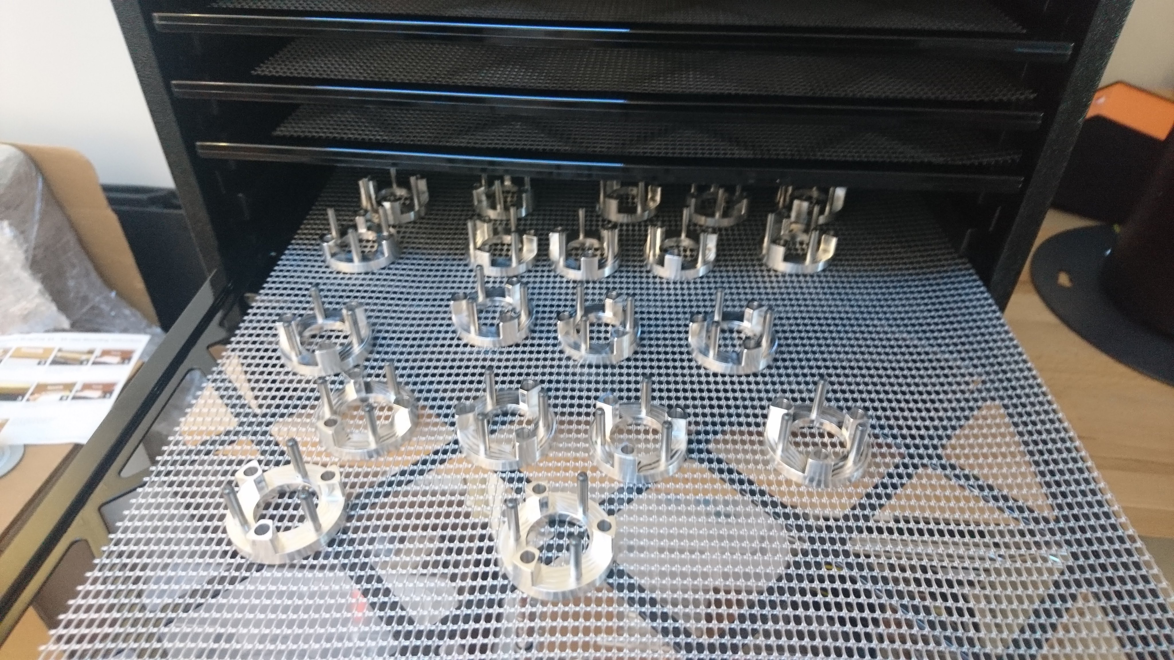
One of the parts on the original quad A0’s leg that was prone to failure was the “knee stud”, a little cylinder that acted as the mating interface between the upper leg and the lower leg.  It directly attaches to the upper leg, and has bearings that ride between it and the lower leg.  The entire tension of the leg belt is born in shear by this part.

20200206-knee-stud

In the mk1 leg, this part was 3d printed with heat set inserts used to form the threaded holes.  This mostly worked, although occasionally the stud could shear along the 3d printed lamination lines.  Thus, for the mk2 leg, I’m making this part out of 6061.

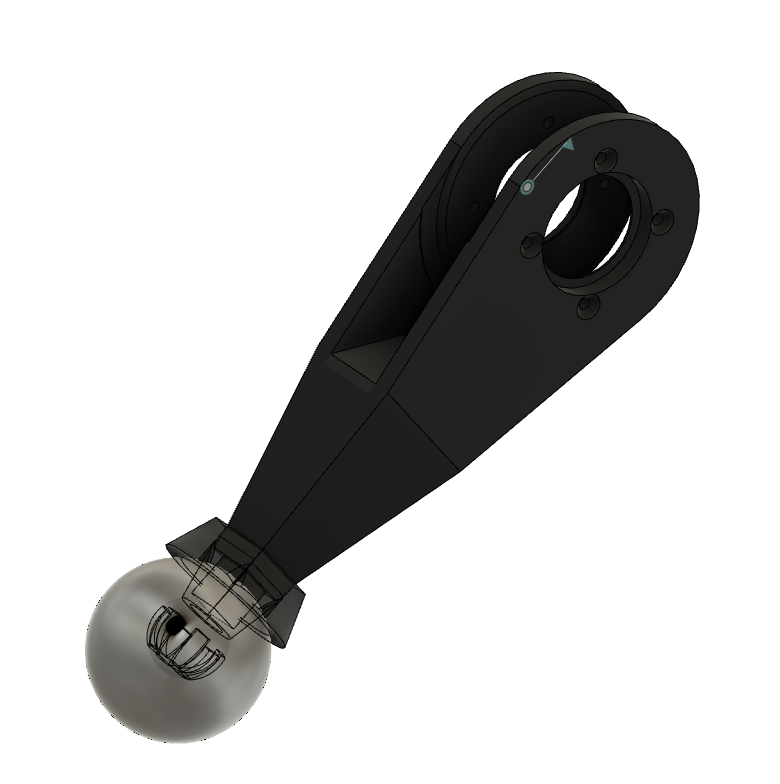
Updated leg design for mk2 servo

Since the mk2 moteus servo has slightly different dimensions and a different mounting pattern than my original, I needed up update the full rotation leg design to handle it.  The basic concept is the same, except for some in-progress work on the foot design which I’ll write up later.  The only significant changes were that because of the mk2 design, access to the power and data connectors is much easier.

Here’s a brief CAD snapshot:

New quad power distribution board

Finally returning back to other pieces of my quad roadmap, I finished getting an updated power distribution board ready for the quad A0.  This board is one I had made many months ago and mostly brought up, but then didn’t quite finish.  The r1 was when I first discovered my unfortunate stm32g4 pinout problems that doomed 3 of my in flight boards.  The pictures here are of r2, which suffered from yet more pinout problems, resulting in more than my usual number of blue wires.  Fortunately, identifying those problems here let me fix them ahead of time for the fdcanusb and moteus r4 boards.

fdcanusb enclosure

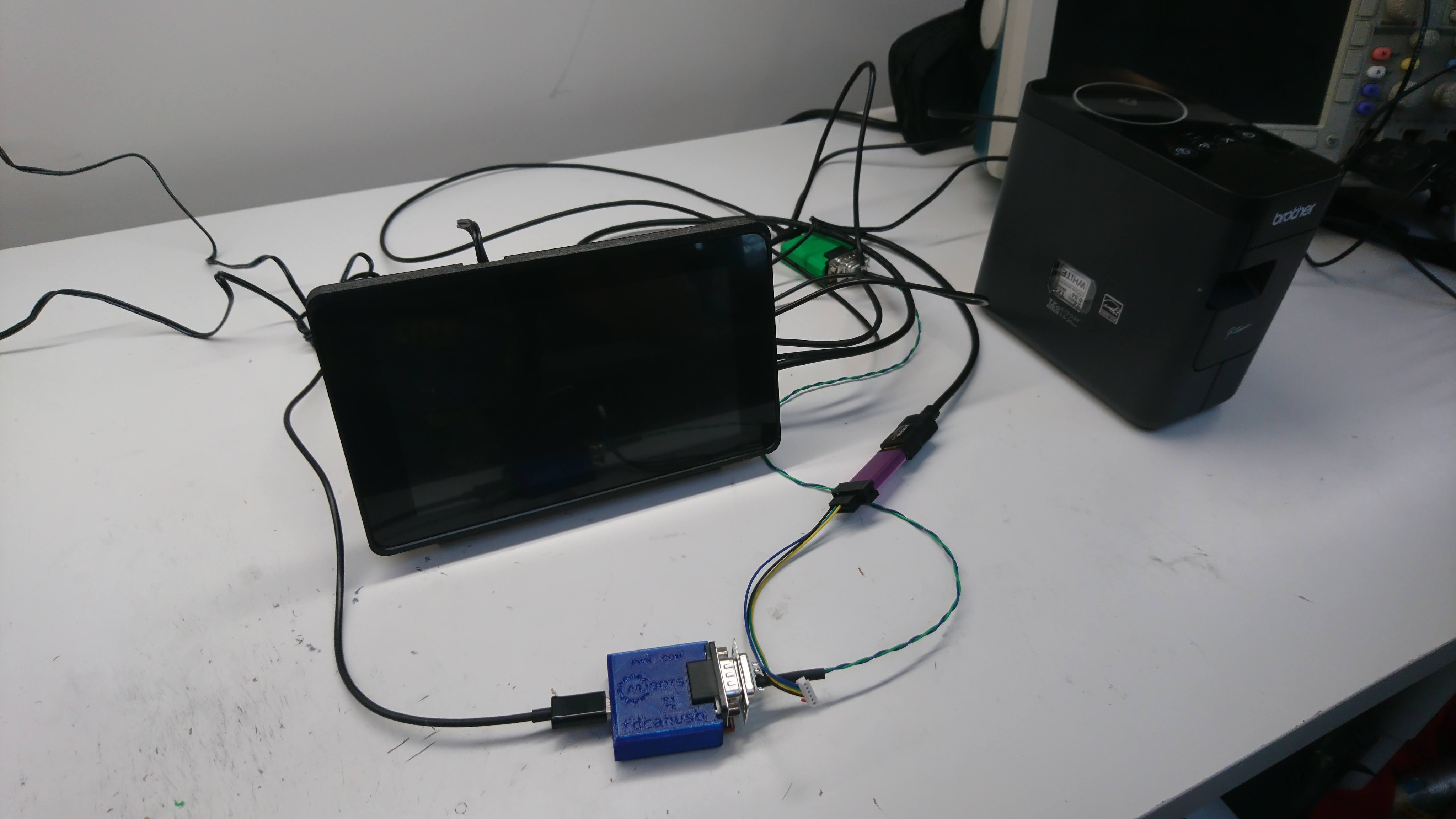
To get ready for initial limited production of the fdcanusb I wanted to make some kind of enclosure so that you didn’t have to just grab the raw PCB and risk ESD failures.  I also wanted to be able to expose the status LEDs without having to do a window or anything else with multiple materials.

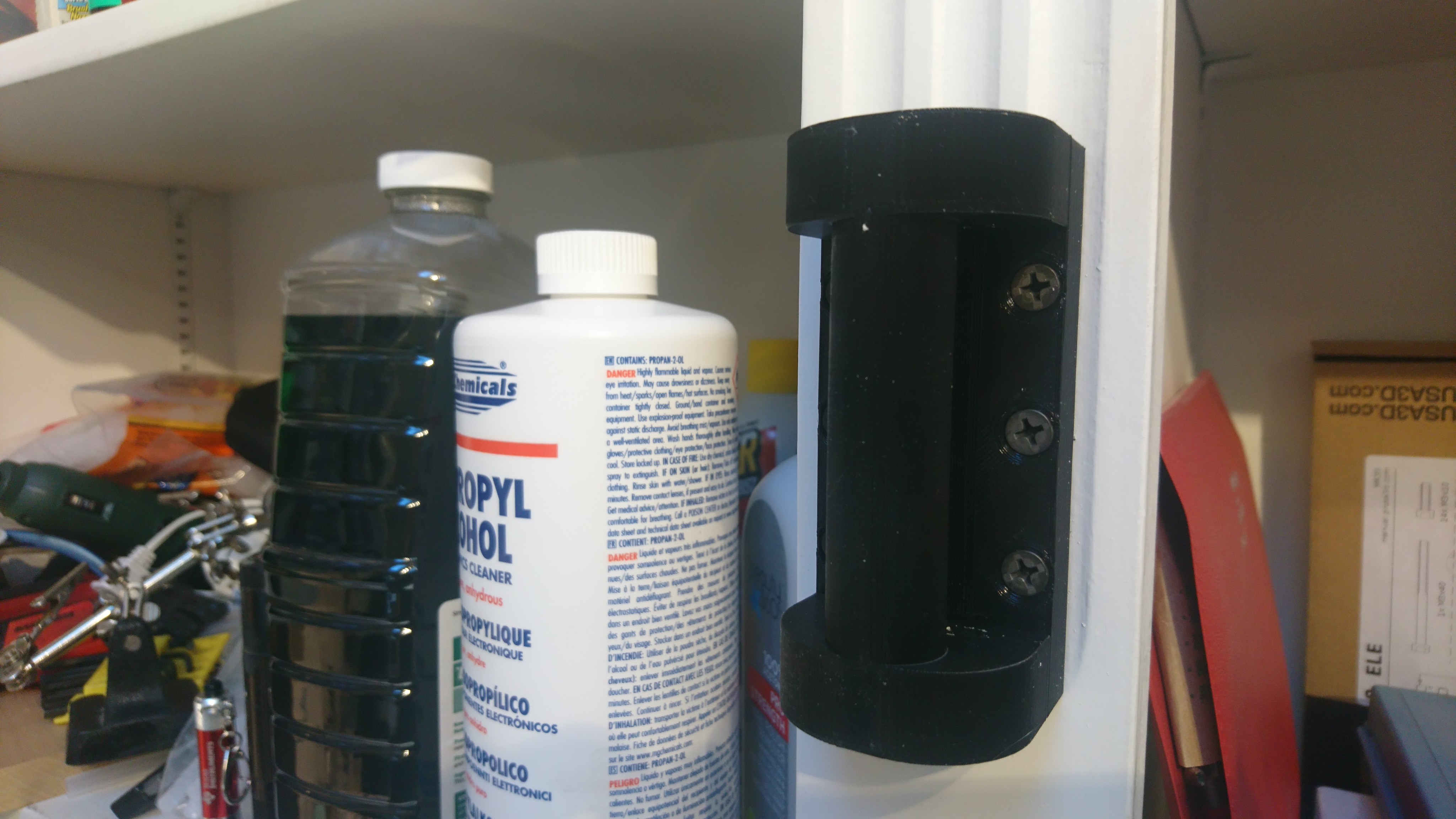
So for now, I just used a translucent PETG print, with light pipes and a thin wall above each of the LEDs.  The result isn’t too bad, you can clearly see the status LEDs and it feels plenty rugged for desk work.

CAN bootloader for moteus r4.x

One final piece of porting that needed to happen for the moteus controller r4.x series was the bootloader.  The r3.x series has a bootloader, which allowed re-flashing the device over the normal data link, but that was largely specific to the RS485 and mjlib/multiplex framing format.  Thus, while not particularly challenging, I needed to update it for the FD-CAN interface used on the r4.x board.

The update itself was straightforward: https://github.com/mjbots/moteus/compare/406f01…1123a9

For now, on the assumption I will in the not too distant future deprecate the r3.x series, just duplicated the entire bootloader, replacing all the communication bits with FDCAN and stm32g4 appropriate pieces.  As before, this bootloader is designed to only operate after the normal firmware has initialized the device, and also is required to be completely standalone.  To make code size easier to manage, it makes no calls to any ST HAL library and manipulates everything it needs purely through the register definitions.

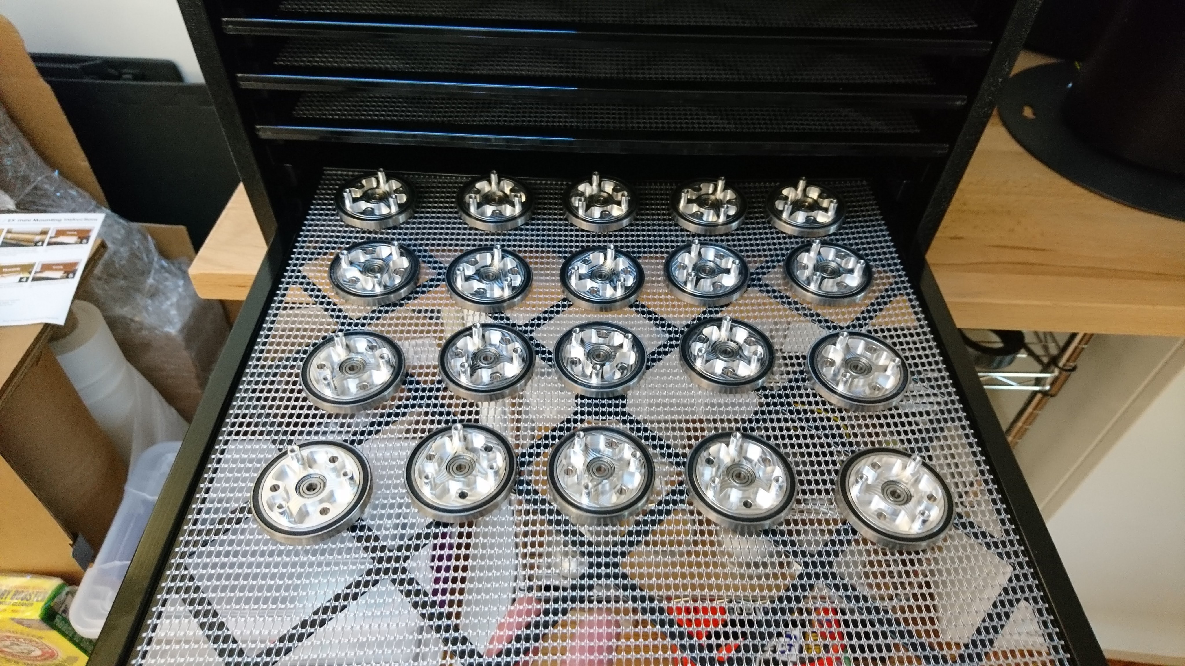
Making the reduced weight servo mk2

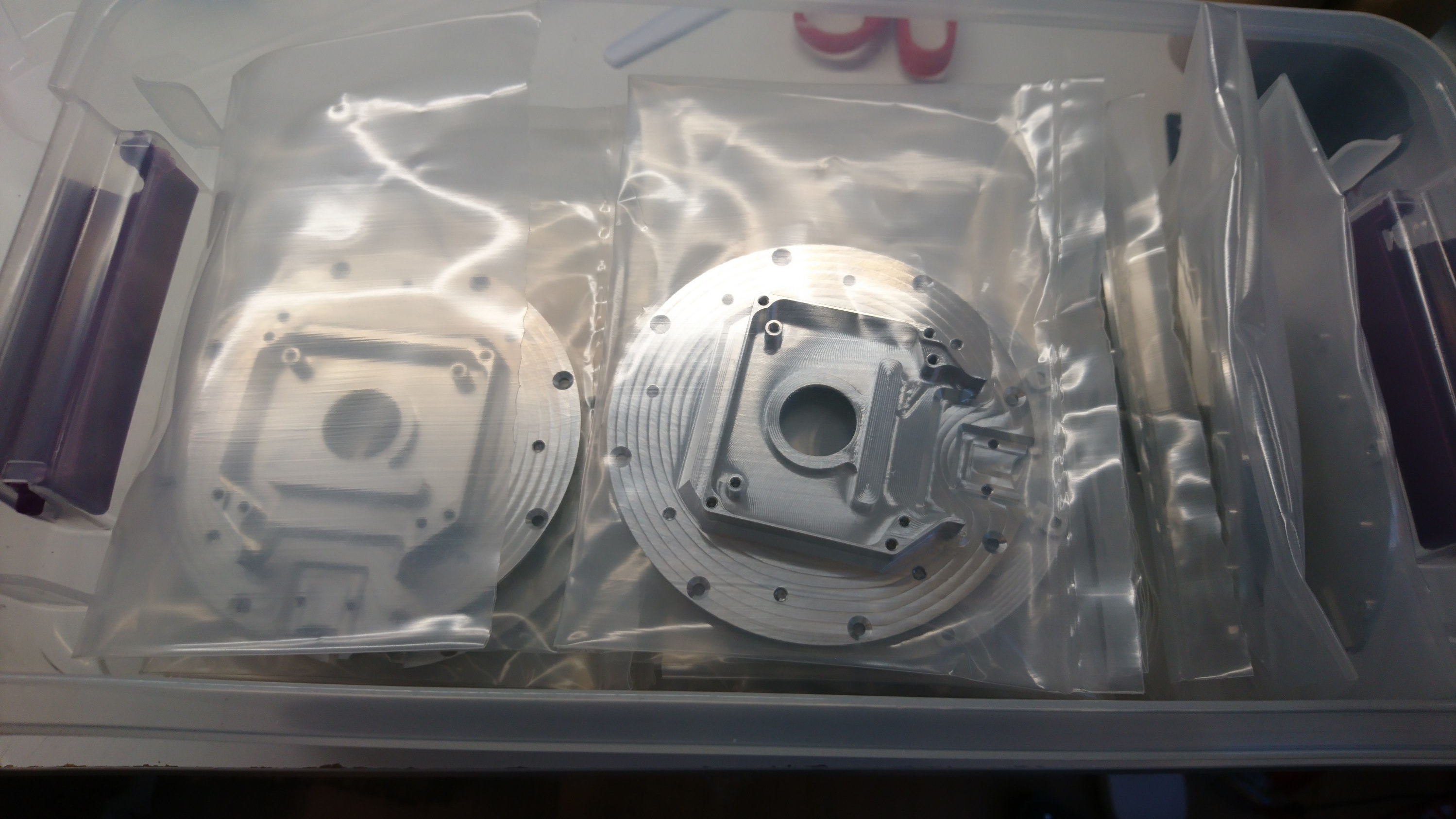
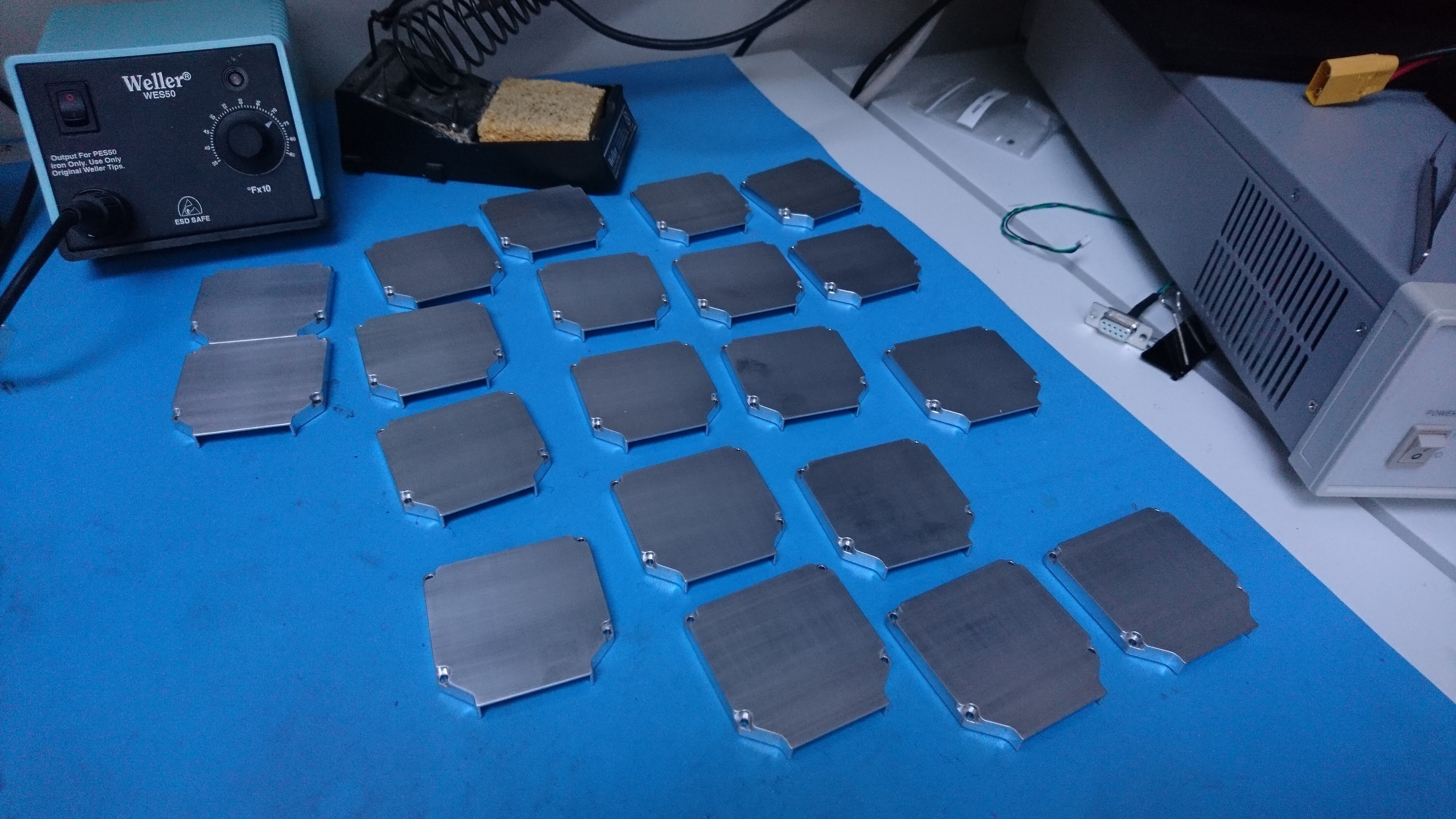
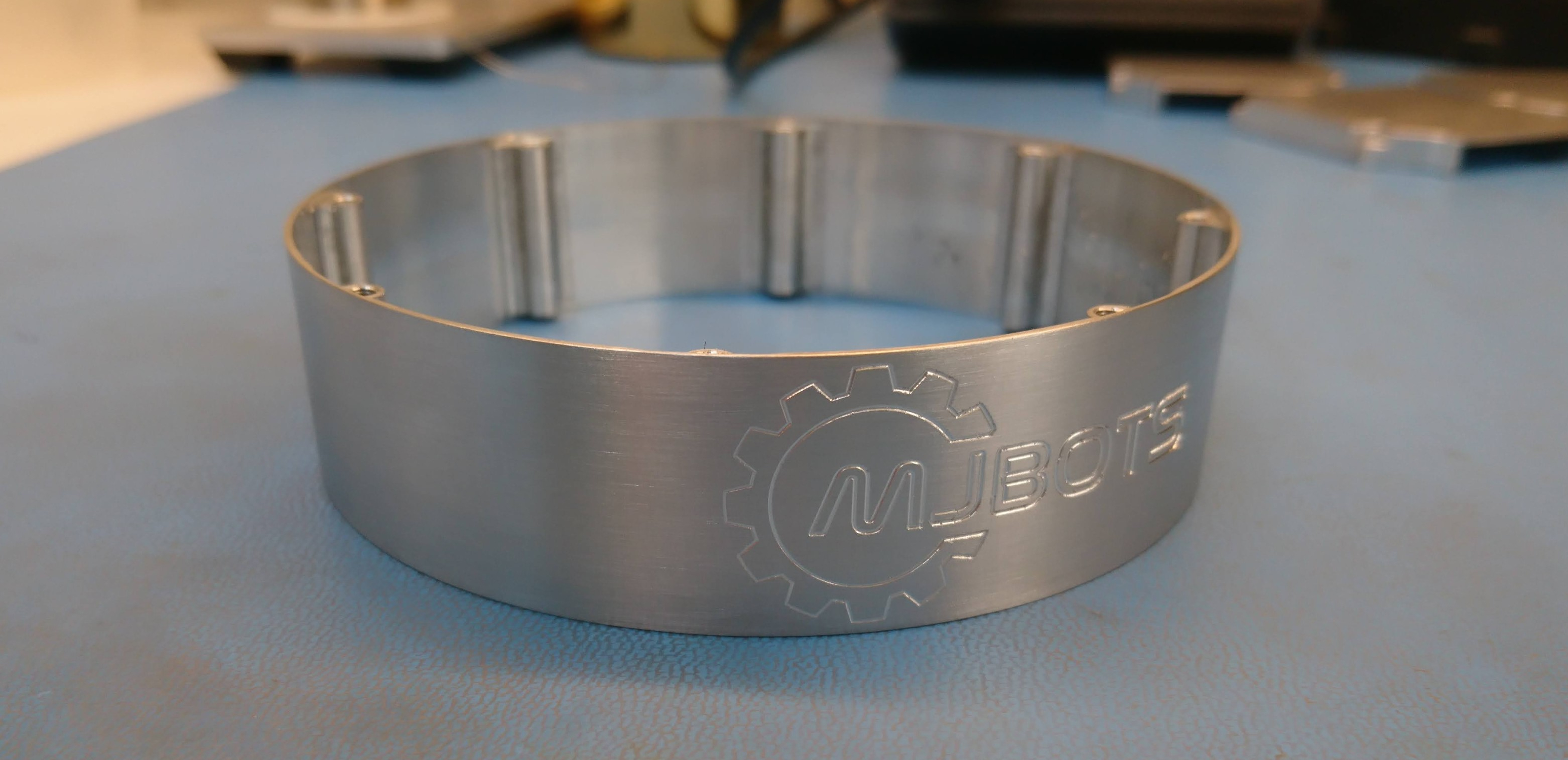
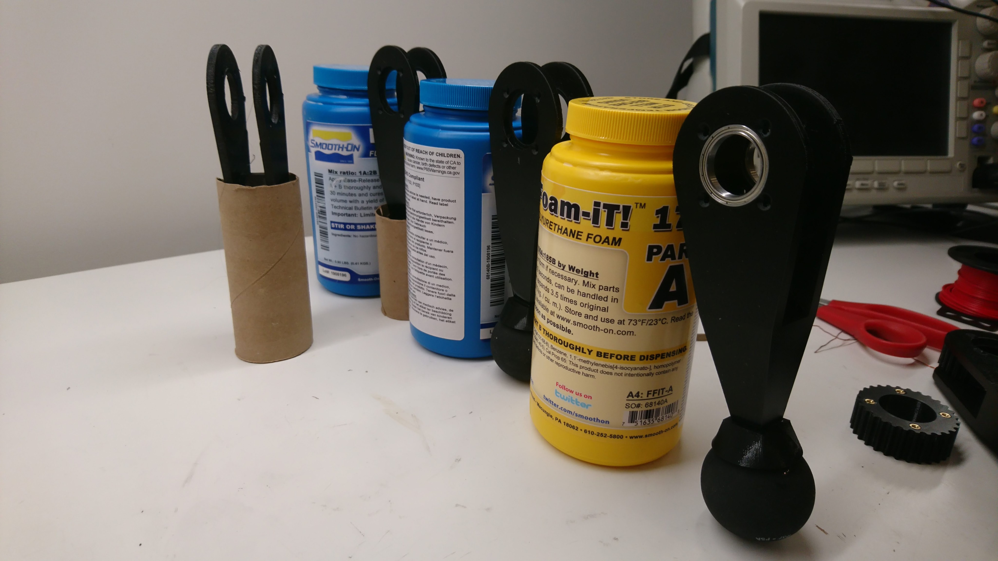
Earlier I described my design plan for reducing the overall mass of the moteus servo mk2.  Constructing a prototype of this turned out to take many more iterations and time than I had expected!  Along the way I produced and scrapped two front housings, two outer housings and a back housing.

Soooo much PocketNC time for naught!

Soooo much PocketNC time for naught!

I made one complete prototype which only had the weight reduction applied to some of the parts and lacked a back cover and any provision for a wire cover.  It was the one from the moteus controller r4.1 juggling video:

C++20 coroutines and moteus_tool

I’ve had a confusing mismash of development tools for the moteus servos for a while now.  My original development tool was in python, which worked just fine.  Coroutines allowed me to express complex asynchronous logic succinctly, the program itself was rather simple, and I could easily integrate it with matplotlib for plotting.  However, when looking to run this on the raspberry pi, I needed a newer python version than came with raspbian, which turned out to be a royal pain to get installed in a repeatable manner.  Thus I rewrote a portion of the moteus_tool in C++ and just used my normal cross-compiling toolchain to generate the binaries.  What I didn’t do was port the calibration logic, as the state machine required with standard boost::asio would have bloated the logic size by 5x, and I didn’t really need to calibrate servos from the raspberry pi ever.

Moteus controller devkit PCBs in house

Update 2020-01-15: All the development kit slots are full.  Thanks for your interest!

I’ve now received all the supplies I need to make up development kits for the moteus controller and to make a test quadruped!

I’m planning on making a few development kits from this production run so others can experiment with the moteus brushless controllers.  Some people have already expressed interest in getting one – you have hopefully been contacted earlier.  If you are interested in getting an opportunity to buy an early access kit and haven’t heard from me yet, fill out this form!