quad A1 chassis updates
I finally got around to fixing a number of minor glitches in the quad A1’s chassis recently.
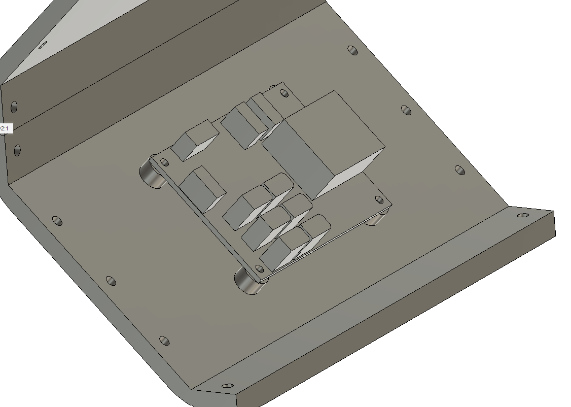
1. The raspberry pi is now far enough away from the left panel that you can connect the HDMI if you choose.
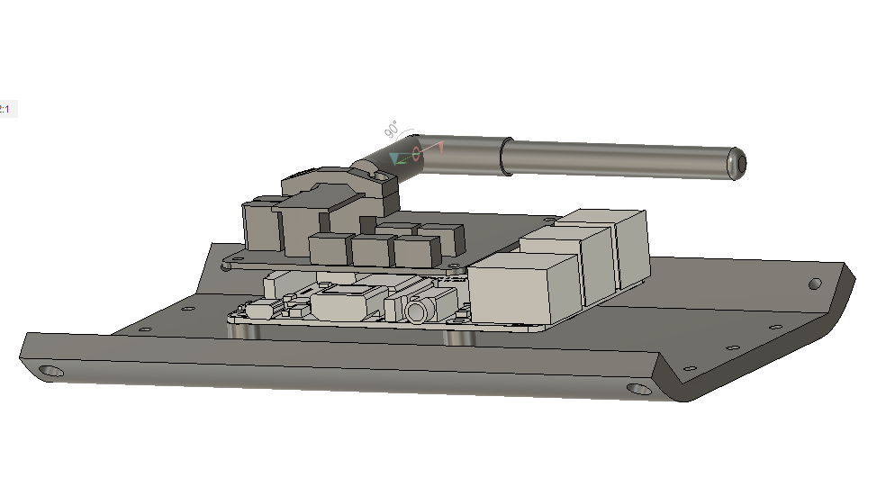
2. I no longer have vestigal studs for the pre quad A0 junction board on the other side.
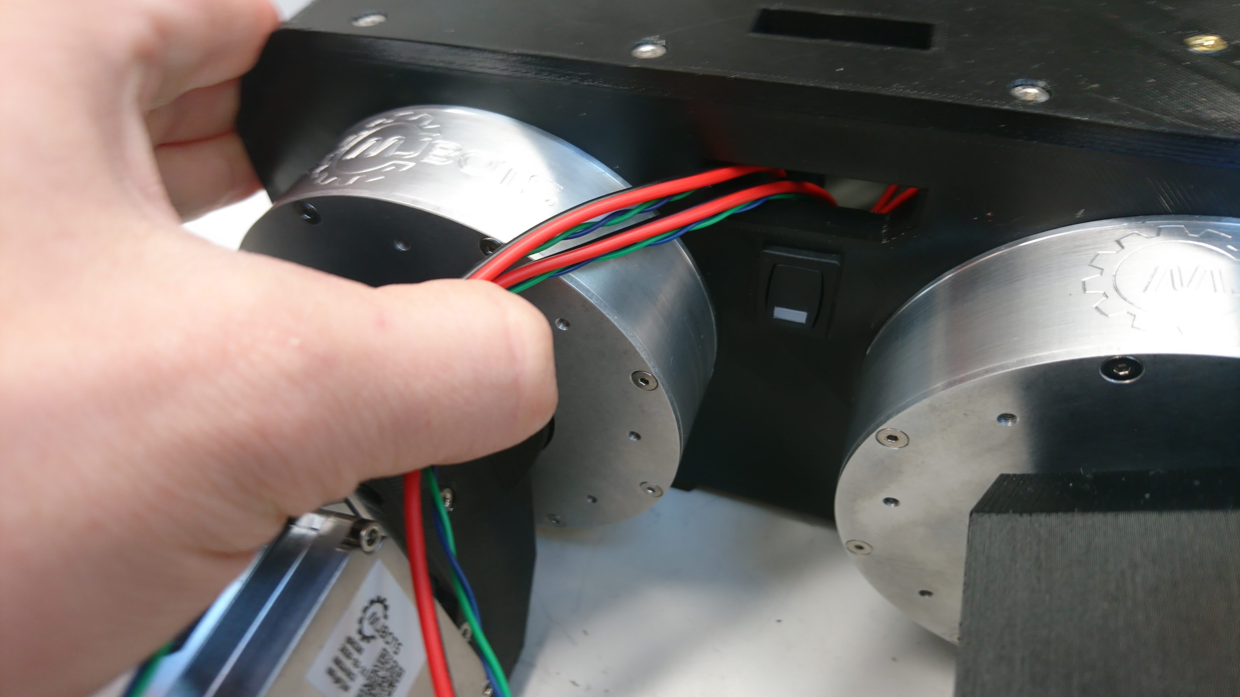
3. The switch got moved down to between the legs.