moteus hardware ADC triggering
TLDR: As of firmware 2026-01-21 moteus now has a maximum modulation depth that is 6% larger than before. That means the maximum speed for a given voltage is that much higher. Read on for the effort invested in making that happen.
Background
The moteus line of controllers all have integrated low side current sensors on each of the motor phases. These are used to provide closed loop current and torque control to the driven motor. Being “low side” they are implemented with current shunt resistors connected between the low side MOSFET and ground, with an amplification stage before being passed to the microcontroller.
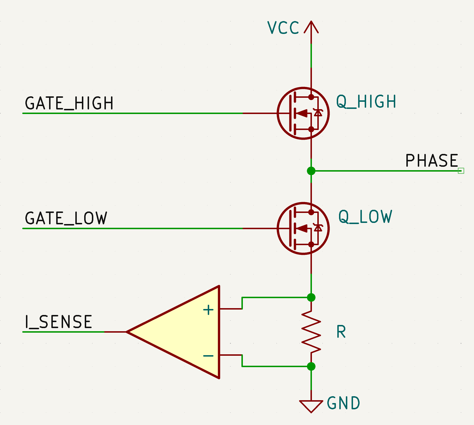
A typical half H-bridge schematic
Notably, the current does not always flow through the low side of each phase – sometimes it flows through the high side, amazing I know! In a normal switching waveform there is some portion of the duty cycle where the high side MOSFET is active and some period where the low side MOSFET is active. Only when that low side is active will current be flowing through the current sense resistor. To make this work, moteus uses a center-aligned SVPWM (space vector pulse width modulation) modulation strategy. That means that the center of the low side activation will be aligned for all three phases. The goal is then to sample all three current sensing channels during that time when the low-side MOSFETS are turned and current is actually flowing through the current sense shunts.
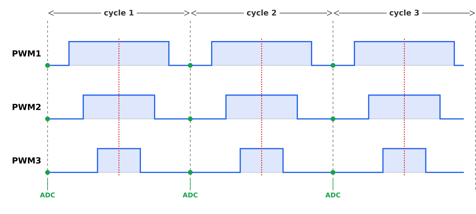
Center-aligned PWM with ADC sampling
This approach does have a limitation, which is common to many field oriented controllers, in that the maximum modulation can never be 100%. If it were, then there would be cycles where some of the low side MOSFETs were not active at all, or not active for a sufficient amount of time to sample the current. To function, the modulation depth, or maximum PWM duty cycle, must be kept low enough such that the current measurement process always has time to complete.
Since the very first board, moteus has used roughly the same strategy to trigger the analog to digital converters (ADCs) in order to achieve this. The primary interrupt service routine is configured to execute at the center of the low side switching waveform. (Technically also the center of the high side as well, but that is ignored in software). Then, in software, the ADCs are triggered. When the sampling phase of the ADC process is complete, moteus samples the PWM outputs for all three phases and ensures that they are all still low.
This worked, and was relatively simple, but it was not optimal from a perspective of minimizing the time required to sample the current. There are a number of events that have to happen between the center of the PWM cycle and the ADC start bit being signalled. The microcontroller must accept the interrupt and start executing the interrupt service routine (ISR) which takes some number of clock cycles. Then the ISR preamble needs to execute in order to save the contents of registers that may be modified. Then the software needs to check whether the direction of the timer is such that we are activating the low side MOSFETs, and whether, if a higher PWM frequency is configured, this is the alternating cycle where control is executed. All those things add up to latency which limits the maximum modulation depth.
Most microcontrollers designed for motor control have sophisticated systems designed to allow much of the hardware orchestration to happen without needing to execute software at all. For instance, the STM32G4 that moteus uses has many ways to trigger the ADCs. In the past the firmware manually set the start bit for each ADC (which caused some of its own problems part 1 and part 2), and until recently used the LPTIM1 peripheral in one shot mode to trigger all of them simultaneously.
Hardware triggering
All this background is there to say that, as of firmware 2026-01-21, moteus now uses a fully hardware mechanism to trigger the ADCs, increasing the effectively maximum modulation depth by around 6%. The biggest win for this is increased maximum speed for the same input voltage, although in some cases the modulation depth also limited the maximum current or torque that could be applied.
The code to implement this strategy is not all that involved, but devising a means to do so was non-trivial. The current moteus firmware supports boards that were developed over the last 8 years, none of which had pins selected specifically for this purpose. Thus, the hardware timer peripheral that the moteus firmware uses for PWM actually has no mechanism to directly trigger the ADCs in center aligned mode. The STMG4 has more than a dozen different timers, so maybe I should cut my 8 year younger self some slack?
The approach that was used is a bit convoluted, and is slightly slower than optimal, but is effective. Working backward, the LPTIM1 timer is still used in one shot mode to trigger all the ADCs. However, instead of manually initating the LPTIM1 timer in software, a DMA channel is used to transfer a word to the control register of the LPTIM1 timer. Then, the PWM timer is configured to automatically initiate the DMA transfer at the center of the low waveform using the compare and capture mechanism.
PWM TIMER -> DMA -> LPTIM1 -> ADC
This does have an additional complication, because in moteus one of the ADCs was sampled twice per control cycle to measure auxiliary things like motor and FET temperature. Now that all ADCs are always triggered simultaneously, that auxiliary data is instead just read every other control cycle.
Side diversion
The initial version of this change used the existing timer update event to trigger the DMA, which resulted in the ADC sampling at both the center of the high point of the waveform and the center of the low point in the waveform. This in theory should have been about equivalent, passed all initial testing, and was committed and released in firmware 2026-01-16. However, after releasing and doing more cross-board characterization, I found that this formulation results in slightly more noise and scale errors on the current sense ADCs. Thus, the further update which uses the compare trigger so that only one sample per cycle is performed.
I suspect, the decreased performance is because the sample time on those current sense ADCs are a bit on the low side. In the common case, where the ADCs sample at roughly the same value each cycle, this would result in less noise and error. Given that this performance has been usable on moteus for some time, I figured keeping it the same is probably “good enough for now”.
Credits
I’ve mentioned my use of Claude Code (CC) with respect to the moteus performance analysis tool in the past. This effort at changing the ADC triggering used some of my efforts to get CC to be more useful in embedded development generally. Combined with Opus 4.5, I have developed some local skills that allow CC to effectively read subsections of the STM32G4 reference manual and errata sheet. Here, I used it to brainstorm ideas for how to get a hardware trigger working and it was surprisingly effective at munging through the datasheet to come up with possibilities. The code itself was also largely generated with CC, although lots of iteration and manual tweaks were still involved as CC does not have sufficient context yet to understand all the limitations in the moteus firmware.
I have also started to have some success getting CC to operate gdb over a remote target. Being able to usefully run and inspect the state of the software under construction makes CC (and, well any developer) much much more effective at completing a given task. For most of this work, I was the hands at the keyboard operating the debugger, but in the future maybe less so.
Future work
There are other avenues that can be used to improve the maximum modulation depth even more, but none are particularly easy.
If alternate PWM pins were selected, then the HRTIM peripheral on the STM32G4 could be used. That can both directly trigger the ADC and has more control over the timing, such that the ADC sampling could be timed to occur centered over the low side waveform, rather than only starting at the center.
There are also documented approaches in the literature to achieve basically 100% modulation depth, through a number of strategies. Some temporarily adjust the PWM waveforms such that at least two phases are always observable, others rely on motor models so that the results of even 1 phase can be incorporated into an estimate of all three phase currents.
It is hard to say if any future work along these lines will be warranted, but you never know!
Upgrading
To upgrade, follow the instructions in the reference manual, roughly this:
Download the latest firmware from https://github.com/mjbots/moteus/releases
Get the file named YYYYMMDD-moteus-HASH.elf
Issue the following command.
python3 -m moteus.moteus_tool --target 1 --flash path/to/file.elf
The moteus performance analysis tool has also been updated with a new performance model for moteus controllers that captures the increased modulation depth. While I was at it, I also finally got it to model the dependency of the modulation depth on selected PWM frequency. Lower PWM frequencies mean that the fixed time needed to sample the current occupies a smaller percentage of the overall duty cycle, resulting in a slightly higher maximum modulation depth.