Optimizing fast movements
In a mini-project inspired by a Discord chat about a Rubik’s cube solver, I decided to undertake a project to see how quickly I could get moteus to make a controlled 90 degree movement and a controlled 180 degree movement. The project ended up involving a fair amount more work and theory than I had expected, but resulted in an overall solution that is relatively close to optimal for the specified moteus and motor. If you find text too hard, you can watch the video below, otherwise read on to see the details:
Premise and background
The initial requestor was looking to get a moteus-r4 to move an Eagle Power 8308 motor 90 degrees and 180 degrees from start to stop as quickly as possible. Granted, this system isn’t going to break the current Guiness Record for a Rubik’s solver, (although conceivably a moteus could assuming a different moteus and motor selection) but it is still a worthwhile challenge to get moteus to move as fast as is possible within the limits of the power supply, the moteus limits and the physical limits of the motor itself. Rather than starting by describing the winding path I took at solving this, I’m instead going to describe what an optimal system would look like, what limiting factors exist and then how each of them can be mitigated. Only after that will I describe my path to the best results I’ve achieved so far.
For any movement that starts and ends at zero velocity, the optimal movement profile will be roughly: a) accelerate as fast as possible, b) possibly coast at the maximum possible velocity, c) decelerate as fast as possible. Many things can get in the way of achieving this “optimal” profile though. Let’s look at them each:
Motor torque: The torque that a motor produces is related to the phase current. For motors with an iron stator, the torque will go up linearly with current until the stator begins saturating, at which torque production drops off rapidly with increasing current. Thus the peak torque is usually limited by the maximum current the controller can emit at a given operating point, which is biased toward the non-saturated region.
There are some factors that could come into consideration, but are less likely. It may be possible to create a sufficiently large magnetic field to demagnetize the rotor magnets. For short, millisecond level events, thermal heating in the motor windings are unlikely to be a constraint, but would be a factor for longer durations.
Motor inertia: Whatever the peak torque the motor can produce, it
will only translate into an angular acceleration depending upon the
moment of inertia of the rotor. Like the linear F=ma, angular
acceleration can be determined by dividing the applied torque by the
moment of inertia. Thus, we ultimately want a motor with the lowest
angular inertia possible, or at least the highest ratio of peak torque
to moment of inertia.
Motor maximum speed: There are several factors that can limit the maximum speed of the motor. The most likely to result in limiting here is the back EMF, or Kv limit. For that, the maximum speed is the input voltage multiplied by the Kv rating multiplied by the controller’s maximum effective duty cycle.
For this project it is unlikely to be a problem, but a motor could also be limited mechanically by the bearings or by thermal heating due to eddy currents in the stator.
Controller current limit: Brushless motor controllers typically have a maximum rated phase current. This may be derated for various factors like supply voltage. Combined with the motor’s current to torque curve, it is possible that this is the limiting factor for torque production.
Controller power limit: Similar to the current limit, a controller may be limited in how much power it can output. For a given torque, the power will increase with speed, as the back EMF increases and eddy current losses increase.
Controller trajectory planning: When performing a motion, different controllers have different methods of determining what torque to apply at what instant to complete the motion. A simple controller may just use a simple PID setpoint, others may use constant acceleration or constant jerk planners. It is conceivable that one could accurately produce the maximal torque subject to all limits for both acceleration and deceleration, although I know of no off the shelf controllers capable of doing this.
Controller motion tracking: When executing a motion, the controller will monitor the position and velocity observed at the output and adjust the applied torque. The rate and stiffness of the gains permitted here will partially determine how quickly the plant can settle.
Controller command rate: If multiple motions are required, such as for solving a Rubik’s cube, those motions must either be commanded with tight timing precision, or scheduled in the controller. In the former, the rate and precision at which commands can be sent matters. If the latter, the speed at which the entire motion sequence can be sent to the controller matters also.
Power supply limits: The DC source for the motor driver likely has a maximum peak power it can provide, along with possible limited transient capability.
Design process
To start with, let’s see where we can get just using the stock
firmware. I started by taking a stock moteus-r4 with default
configuration, calibrating the BE8108 with --cal-bw-hz 800, set the
PD gains about as high as I could reasonably get at kp=20, kd=0.15,
configured the high rate debug
output
to capture position, commanded and desired torque at the full rate,
and then made test moves increasing the acceleration until it stopped
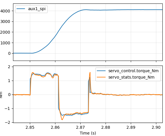
getting better. The best waveform I got looked about like this with
an acceleration of 2000 Hz/s:
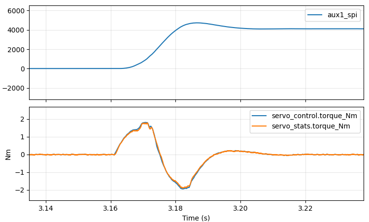
So, around 42 ms from when motion starts until it is stabilized.
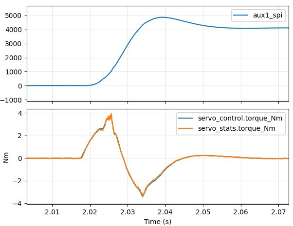
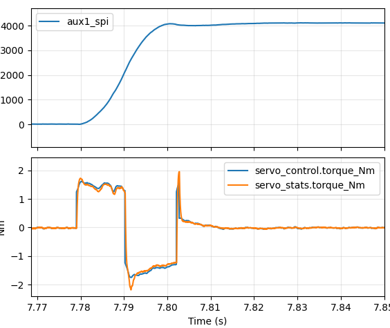
However, if I increased it much beyond that, I started getting waveforms that looked like this:
I noticed two things: first, the torque control was pretty far from
the desired “bang-bang” trajectory and second, at higher
accelerations, the actual torque was not tracking the control torque
all that well. For the latter, it turns out I had neglected to relax
the current control servo.pid_dq.max_desired_rate, which limits the
rate at which the desired current is allowed to change. The default
is 10000A/s, which means that the full positive to negative swing on a
moteus-r4 can be accomplished in 20ms, which is entirely too slow for
what we’re trying here. The limit mostly exists to prevent damage
from poor PID tuning and poor feedforward torque commands. Since I’m
willing to sacrifice controllers in the sake of performance for now, I
just set it to 10000000 A/s, which allows a full +-100A swing in a
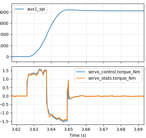
single 30kHz control cycle. Now the optimal acceleration is around
4000 Hz/s and the plot looks like this:
Better at around 37ms, but still not great. In our ideal world, we would command maximum positive torque right until roughly the halfway point, at which point we would command maximum negative torque. The first approach I decided to take was to add an “inertial feedforward” term into moteus. When executing an acceleration limited trajectory, the “control acceleration” is multiplied by an estimate of the total system’s moment of inertia to produce a feedforward torque at each time step. Since moteus implements a constant acceleration planner, that will result in a fixed positive torque until the halfway point, then a fixed negative torque until the final stopped point. That is unlikely to be optimal, as power or speed limits may mean that the achievable torque differs at different speeds, but it is at least a start.
To make that work, I had to model the moment of inertia of the system.
I did so purely through trial and error, sweeping through values and
looking at the resulting motion profiles. Here you can see 5 plots
spanning what I found to the optimal value tested at an acceleration
of 2000 Hz/s. When the moment of inertia is too low, there is
significant overshoot. When it is too high, the motor comes to a stop
too soon and reverses direction as the slower PID controller takes up
the slack. When it is “just right”
(servo.inertia_feedforward=0.000085 kg*m^2 in this instance), the
trajectory nearly exactly matches the optimal and the commanded torque
remains close to constant throughout the motion.

Now for a slight side-tangent. For the inertial feedforward to be
consistent across a range of accelerations, moteus must have an
accurate ability to predict how much torque it will generate at a
range of phase currents. The default --calibrate process will
determine a decent value of Kt for the linear region of torque
production
but that breaks down as the stator begins to saturate. So that I
would not have to re-tune the inertia after each acceleration change,
I now took the time to enter the saturation parameters into moteus
that I calculated for this motor using the procedure described
here.
For reference, those are the ones in
mpat:
rotation_current_cutoff_A=20.50, rotation_current_scale=0.04212,
rotation_torque_scale=1.0255.
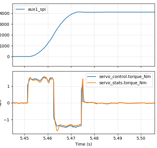
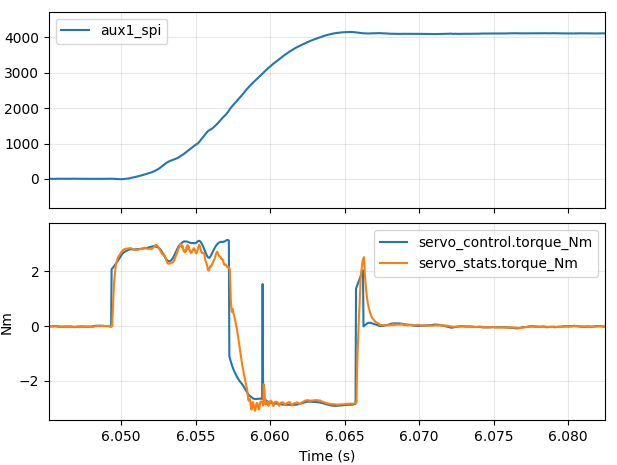
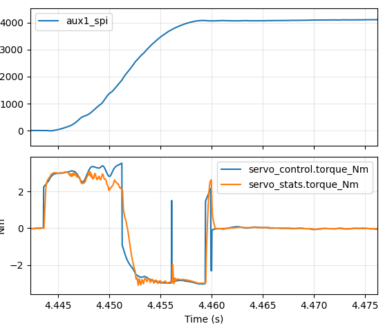
With the relaxed servo.pid_dq.max_desired_rate and tuned saturation
model I re-tuned the inertial feedforward (now with an optimal value
0.000083), then gradually increased the acceleration until the system
started hitting the power limit of the moteus-r4 and the phase current
was no longer able to track the desired. This resulted in a fastest
time of around 16.5ms.
a=2000Hz/s 24ms quarter turn a=4000Hz/s 17ms quarter turn a=4250Hz/s 16.5ms quarter turn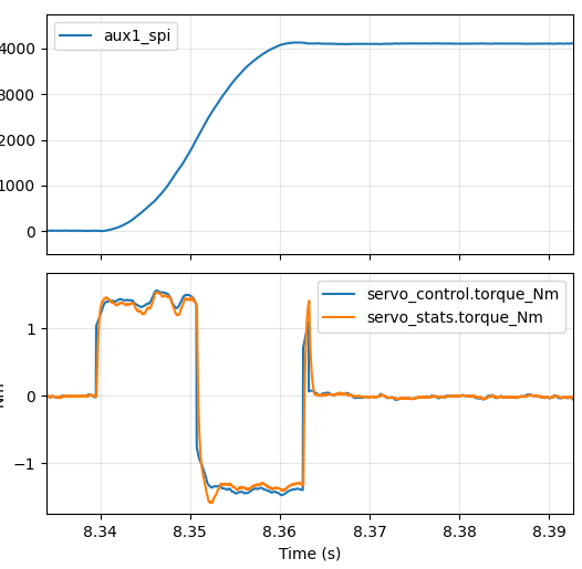
And again for a 180 degree turn:
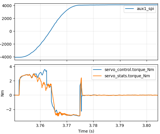
a=4000Hz/s 23.5ms half turn
So, the best result I was able to get for a quarter turn was 16.5ms and for a half turn was 23.5ms
Actual analysis
At this point, I decided it was worth it to use the recently announced mpat tool to try exploring tradeoffs more rapidly than physically wiring things up and looking at innumerable 30kHz data traces.
mpat has many analysis possibilities, although it didn’t yet have an analysis for the question “how quickly can a motor move from one position to another”. So, I made one! It makes some assumptions:
- The controller can perfectly plan a trajectory that uses the peak available torque at every instant. (moteus only supports constant acceleration trajectories)
- The acceleration and deceleration are symmetric.
- Controller and motor thermals are completely ignored. This makes sense for short moves, probably not for long ones.
The analysis is parameterized by move distance and load inertia. To complete the analysis, an estimate of the motor inertia was required as well. I built a simple, somewhat hacky tool, that allowed me with some fiddling to estimate the inertia for all the motors currently modeled in mpat.
The approach mpat uses to estimate minimum move time is to integrate in fixed distance increments, keeping track of total system energy in order to avoid any singularities around 0 speed. It integrates starting from 0 speed until half the distance is covered and then just assumes that deceleration is identical but in reverse as far as peak achievable torques. This is not the case in reality, but is a fine approximation for these purposes.
In addition to the total time required for the move, the analysis also emits averages for all the loss terms, the peak supply power and peak velocity achieved.
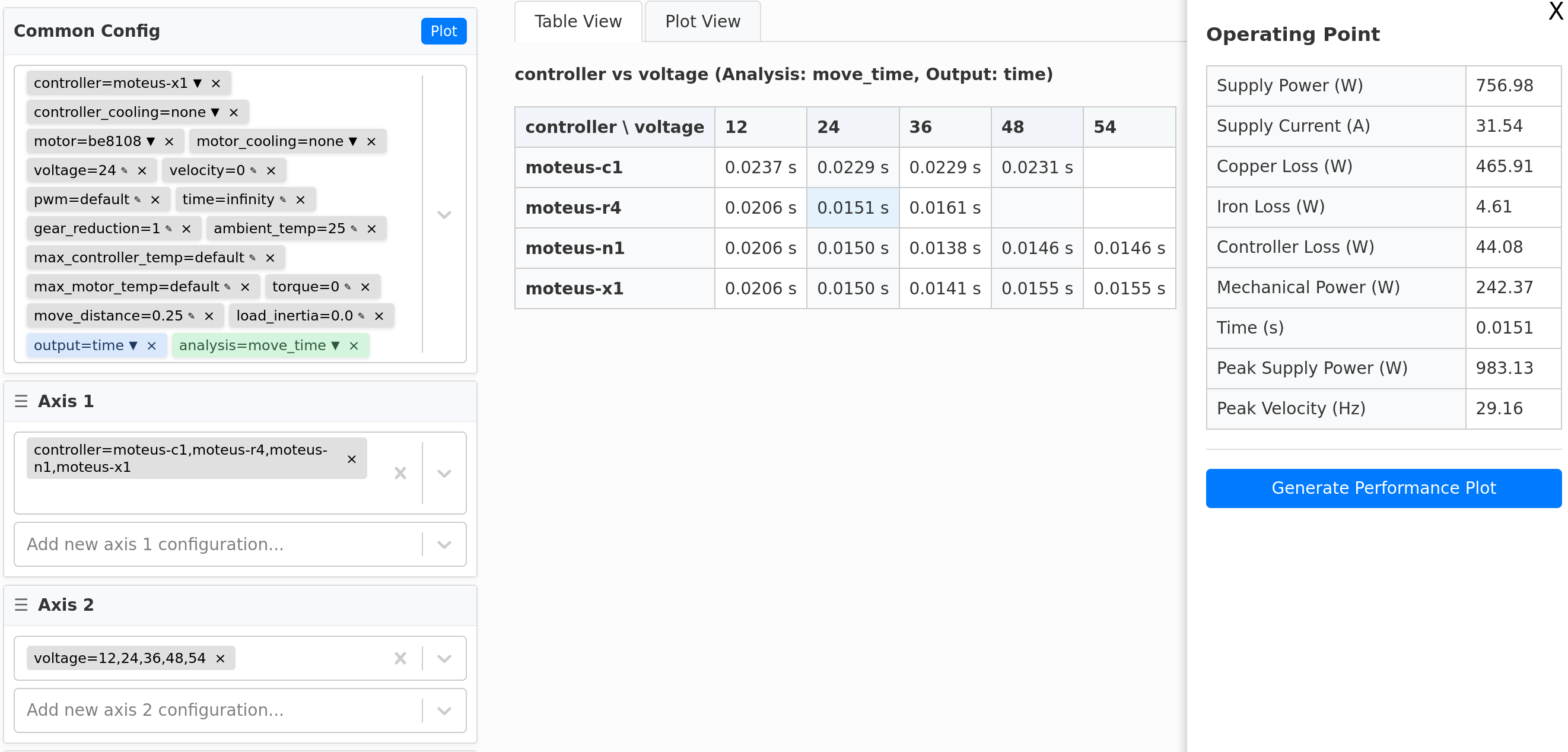
With this tool built, I can pretty easily explore how some other easily controllable parameters would affect the minimum achievable time. I was specifically interested in switching to a moteus-x1 and or changing the PWM frequency in order to get more peak power. Here’s an analysis for the BE8108 across a range of supply voltages, PWM rates, and for both the moteus-r4 and the moteus-x1:
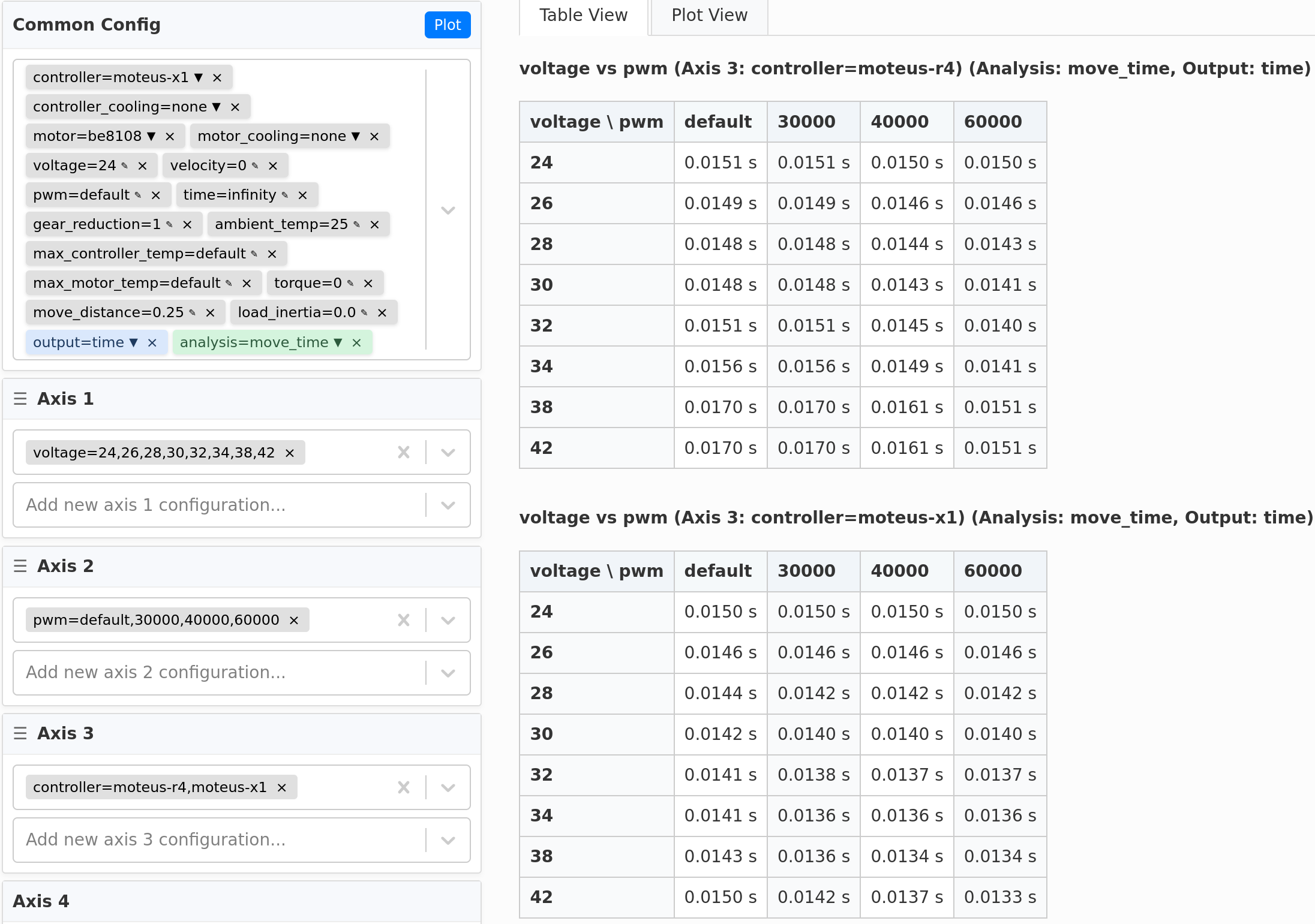
From it, you can see that the optimal time for the moteus-r4 with the default 30kHz PWM rate is around 14.8ms, observed at a voltage of 28-30V, which is pretty close to what we were able to achieve experimentally. The analysis for that point shows an average supply power of 910W during the move.
The overall best time with a moteus-r4 is around 14.0ms if the PWM rate is bumped up to 60kHz. So, that’s around 5% better, and it comes with an average supply power of 1426W, or ~60% higher.
If we switch to the moteus-x1, we can get that time down a little bit more, all the way to 13.4ms when run at 40kHz and 38V supply. At that operating point, the average supply power is 2.2kW with a peak of 2.65kW.
At this point I’ll go ahead and say that going much lower than 15ms with the BE8108 is probably operating in a regime that isn’t particularly efficient for this motor!
Next steps
So, it seems that with a moteus-r4 and a 135Kv BE8108, these physical results I have been able to achieve are likely within a few percent of the best you can do in terms of movement time.
The biggest limiter at this point is the motor design. For fast moves like this, you really want to be using an inrunner motor which maximizes the ratio of torque to moment of inertia, and preferably one with a long stator length and small ID. Additionally, a controller like the moteus-x1 would permit both a higher peak current and a higher peak power, which would both combine to let you move even faster. Some back of the envelope calculations make me think that a custom inrunner design with a moteus-x1 could get a 90 degree turn down to possibly less than the record pace of 5ms while moving a Rubik’s cube face… Who knows?