Archives: 2022-06

Flexible I/O: Sink configuration

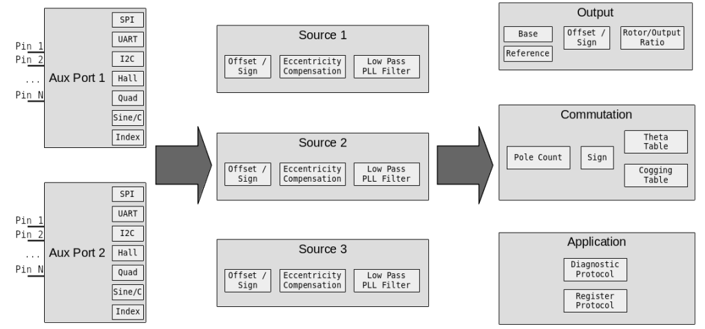
This will be the final post describing the fundamentals of configuring the new flexible I/O system. There have been a number of previous posts (part 1, part 2, part 3). In this iteration, we’ll cover how to configure the sinks that consume the “source” encoder data. As a reminder, the block diagram of the I/O system looks like:

Commutation

To perform commutation with field oriented control, moteus needs to know the relationship between the rotor and stator in the magnetic domain. With the addition of the new flexible I/O system, some of the configurable values associated with this remain as they were, where there are some new ones.

Flexible I/O: Source configuration

In the last two posts (part 1, part 2), I started talking about the new, more flexible I/O subsystem for the open source moteus brushless motor controller. In this post, I’ll continue by describing what a “source” is, and how it is configured.

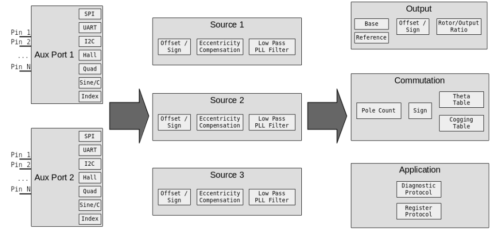
For reference, the block diagram showing how auxiliary ports, sources, and sinks are related is below:

Each “source” in the above diagram represents a single encoder. To the sinks it provides a position and velocity, along with various validity indications for that data. Each has three basic configuration components: where to get the raw data, how to transform that raw data, and the low-pass filter configuration. We’ll cover each in turn.

Flexible I/O: Auxiliary port configuration

In the last post, I covered the goals behind more flexible I/O support in the moteus brushless controller. This time, I’ll start to cover the configuration model that I implemented to make that support work. It is broken up into 3 distinct phases, auxiliary ports, sources, and sinks.

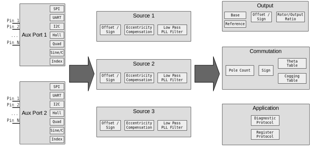
Slightly simplified I/O structure flow diagram

Slightly simplified I/O structure flow diagram

Auxiliary port pin configuration

To begin with, the available connectors and external pins on moteus are organized into “auxiliary ports”. For the moteus r4.3/4.5/4.8/4.11, the correspondence is that the external primary encoder connector, if present (r4.8 and newer), is “auxiliary port 1”. The ABS port and some on-board debug pads are “auxiliary port 2”. For each port, there are two levels of configuration, at the pin level and the function level.

Beginnings of more flexible encoder and I/O support

The moteus controller, being a brushless servo drive, needs to use encoders to measure things like how the rotor is positioned relative the stator, and possibly output shafts that have passed through a reducing stage. The support for this has gradually expanded over time, but is still relatively limited as far as those things go. The available options are:

  • Primary encoder (used for commutation)
    • The onboard AS5047P
    • An external AS5047P
  • Auxiliary encoder (optional, for measuring the output shaft)

However, the moteus hardware has always been capable of more, both because the processor is a very capable one, and the exposed IO pins are relatively flexible. While looking at some future designs that incorporate even more IO options, I decided it was time to update the firmware to finally start taking advantage of that flexibility.