CNC machined planet output and front housing
Shortly after receiving the sun gear holders, I received the first iterations of the planet output and front housing.
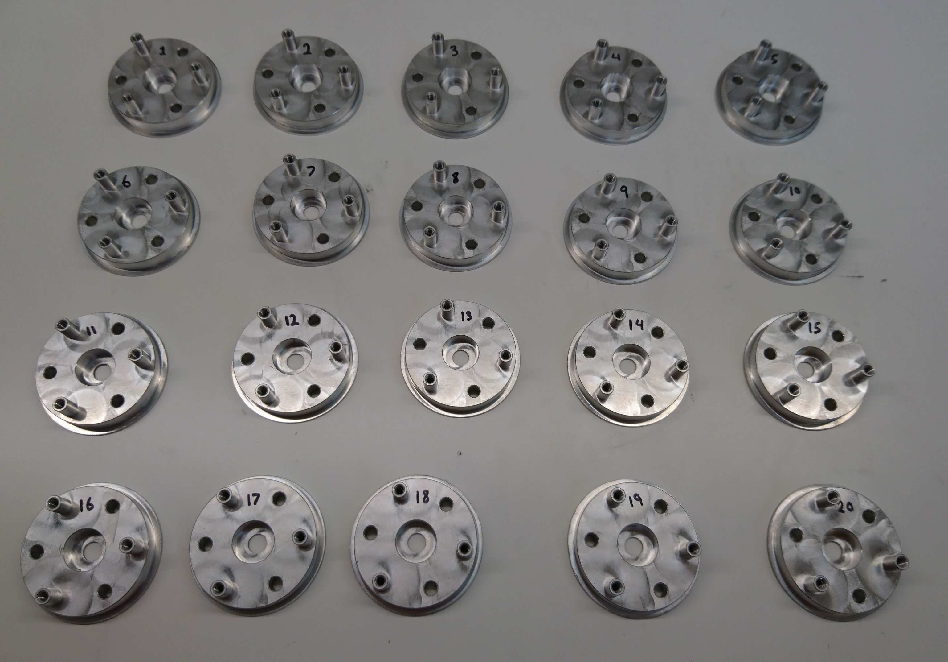
20x of the planet output
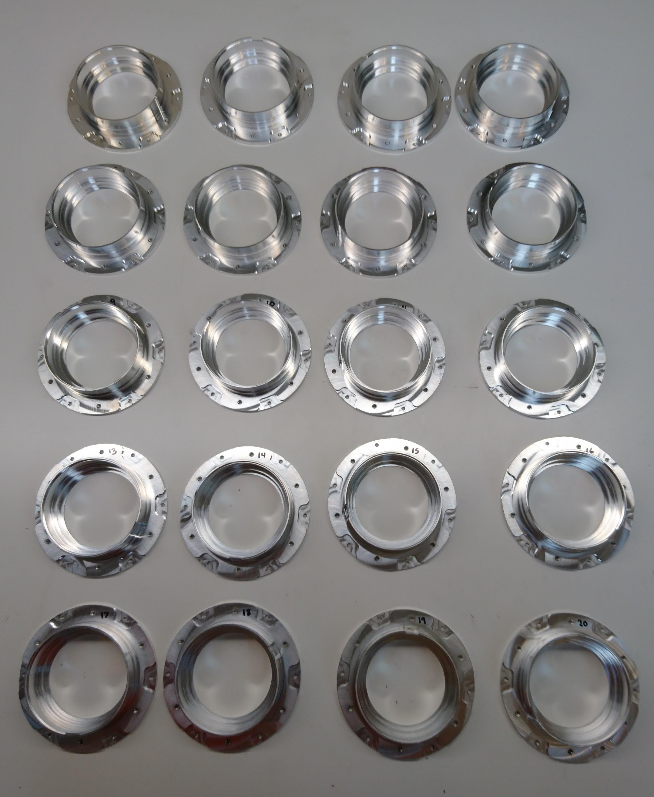
20x front housing
Both of these seem to have actually adhered to the tolerances I requested, so thankfully it won’t be too hard to fit everything together. However, getting everything together for the first time did involve a comedy of errors – a lack of planning for assembly order, a lack of foresight into how things would be *dis-assembled*, a stubbornly stuck shaft, and plenty of broken parts.