Archives: 2019

moteus servo mk2: Back housing

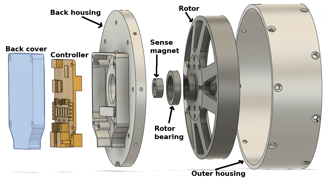
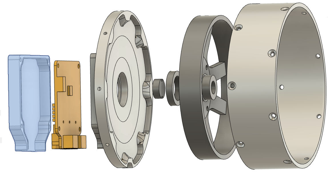
The back housing is the final piece of the moteus mk2 servo that I wanted to prototype.  (The planet output is identical to the mk1, so I could use extra stock I had of it for the prototypes).  It is large, and only mates directly to 4 other things, which makes it a little less complex than the front housing.

back_housing_exploded1.png

back_housing_exploded2.png

Design

I had initially designed the back housing to mate to the as-yet-unannounced new version of the moteus controller, the r4.x series.  Unfortunately, I don’t have any of those working yet, so I tweaked the design to temporarily fit a r3.1 controller, which looks like this:

moteus servo mk2: Front housing

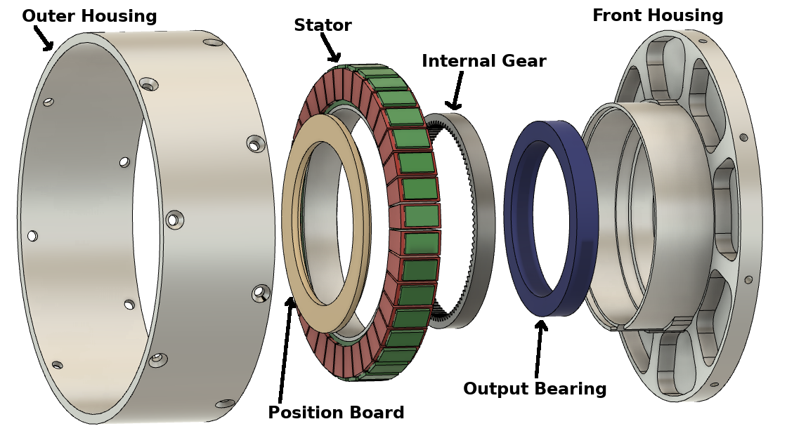
The front housing is the most complex machined piece in the moteus servo mk2, as it was in the mk1.  It is relatively large and mates with many other components with the associated tight tolerance surfaces.  For mk2, the front housing is even larger in diameter, but otherwise has the same basic features.

front_housing_exploded.png

Manufacturing

Building a prototype of this was a real challenge given the tools I have available to me now.  For mk1, I didn’t even try and just had Xometry build my prototypes, and was lucky enough that the first ones worked.  My only CNC currently is the Pocket NC v2-50, which is just barely big enough to deal with this part, and has no convenient workholding that can be used for the stock.  Also, it has a low material removal rate, such that starting from stock here would be prohibitively time consuming.

moteus servo mk2: Outer housing

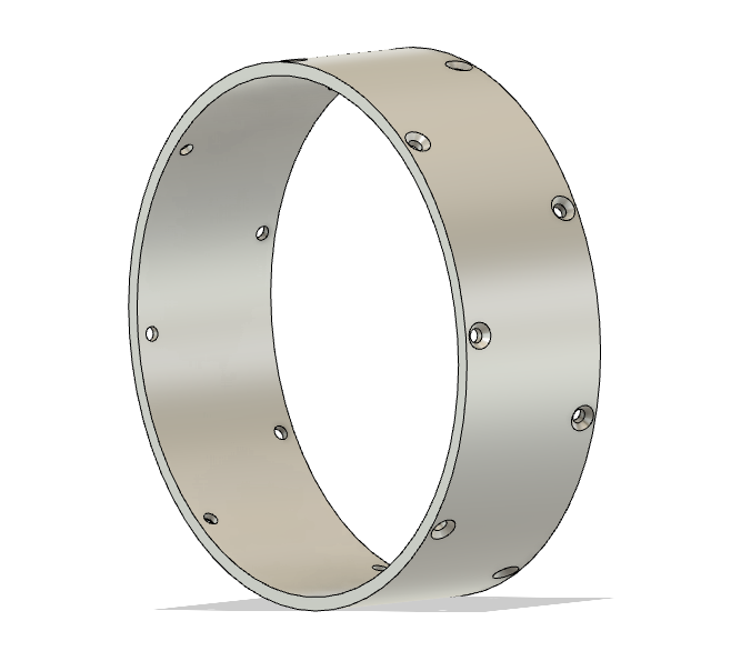
The outer housing for the moteus servo mk2 is just a precision round tube with some mounting holes drilled peripherally.  Still, manufacturing it was slightly annoying, mostly because of my available machining resources.

outer_housing_cad.png

Manufacturing

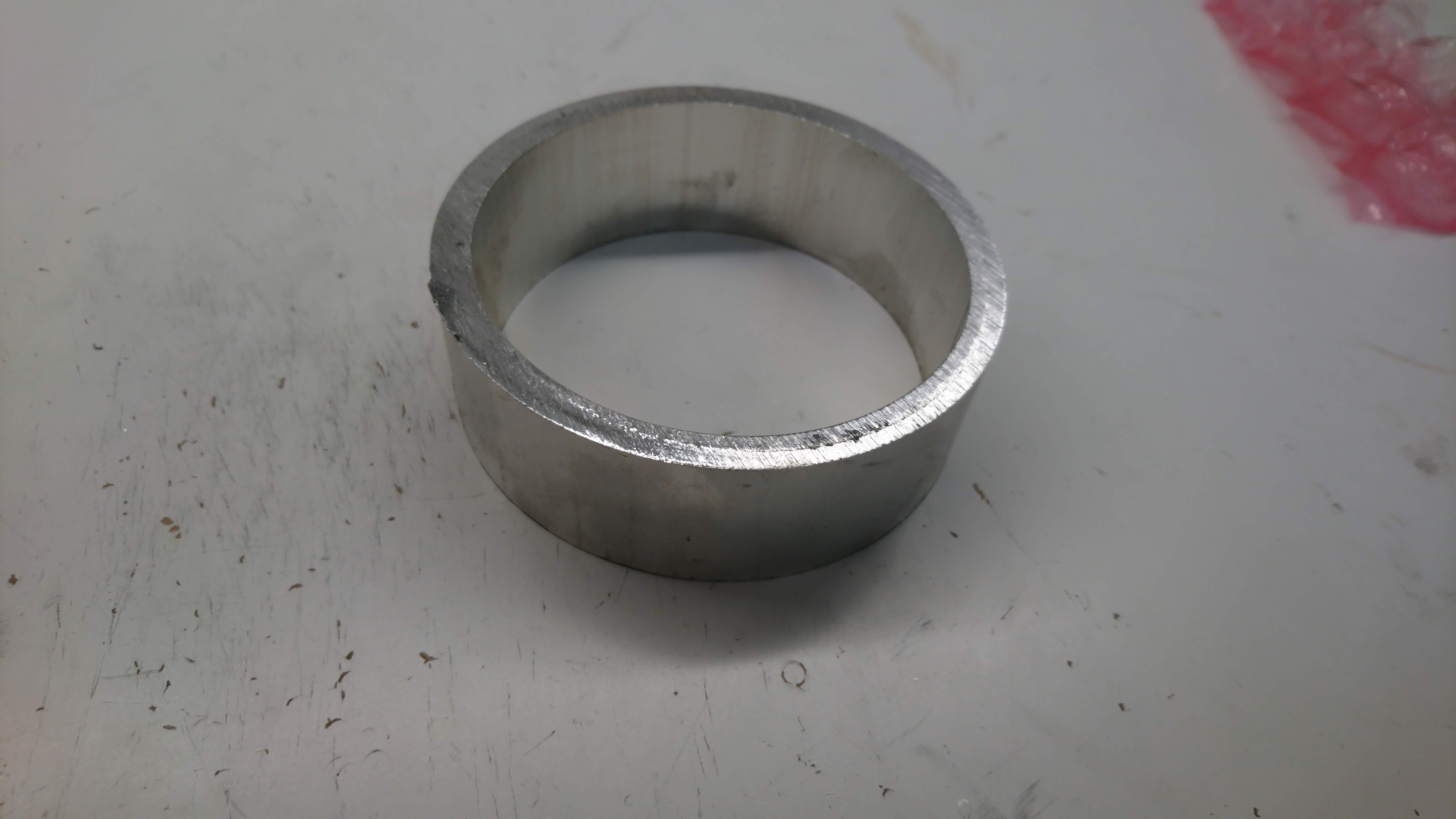
I started off with round tube stock with some extra margin on the inside and outside:

dsc_1789

Then I went and used the manual lathe at Artisan’s Asylum to get the correct ID, OD and length:

moteus servo mk2: Planet Input

As the first part of the new moteus servo mk2, and continuing in my series of learning about CNC by building parts for the quadruped, next up I machined the input to the planet gears on my Pocket NC V2-50.  This was a part, that for my quad A0 build, I used a 3d printed part in PETG as it is probably the least stringent part in the gearbox in terms of tolerances and load, although I still expect the plastic ones will likely wear and fail after some time with heavy use.

moteus servo mk2

As described in my roadmap, making a new revision of the moteus servo is up there on my list of things to do.  The initial servos were a work of art, yes, but also pretty fragile, very labor intensive, and still not all that robust.  My goals this time around are:

  • Manufacturability: The servo mk1 took about 2 or 3 man-days of manufacturing time per servo once all the steps were factored in.  I’d like to get that down to an hour or two at most per servo.
  • Robustness: The planet input, outer housing, back housing, and controller cover of the mk1 servo were 3d printed, mostly to save cost and time.  This necessitated adding reinforcing rings on the outer housing, as it is nearly impossible to 3d print something with the required material properties in a single print.  At this point, all of these components should just be made of aluminum like the others.
  • Repairability: Once the mk1 was assembled, there was no way to disassemble it, as installing the stator interfered with the ability to remove the outer housing, and the outer housing in place interfered with the ability to remove the stator.
  • Convenience: The mk1 servo used the r3.1 moteus controller, which had RS485 connectors sticking straight out the back, and bare power wires coming out the back.  That orientation for connecting things was not terribly convenient in the full rotation leg design, and required making extension cables.  The newer moteus controller has the connectors sticking out the bottom, so the servo needs to accommodate that.

CAD explosion

CAD rendering

CAD rendering

Thread milling on the Pocket NC v2-50

UPDATE 2019-11-27: The feeds and speeds have been tweaked based on further experimentation.

To date I’ve managed to not do any threading on the parts I’ve made on my Pocket NC v2-50.  However, I’m about to do a number that require both M3 and M2.5 threads, so I figured it was time to figure out how to do it.

Online tutorials are kinda all over the place in both how you handle things in the model, and how you program the CAM.  Some assume you model threads as a hole of the major diameter, some as a hole of the minor diameter, although none that I could find used the new Fusion 360 “threaded” hole type, which is what I wanted to use.  That said, using the “threaded” hole type appears to be treated basically as a minor diameter hole with a minor caveat.  You would expect that since Fusion knows the minor and major diameter, the “pitch diameter offset” would be relative to a zero tolerance thread, but in fact it appears to be relative to the minor diameter as if you had modeled a minor diameter hole.  Oh well, I just experimented with increasing pitch diameters until I had threads that fit relatively tight for the two that I cared about, which fortunately can be both made using identical tools, although the M2.5 hole is only on the edge.
Ramping up for moteus servo mk2

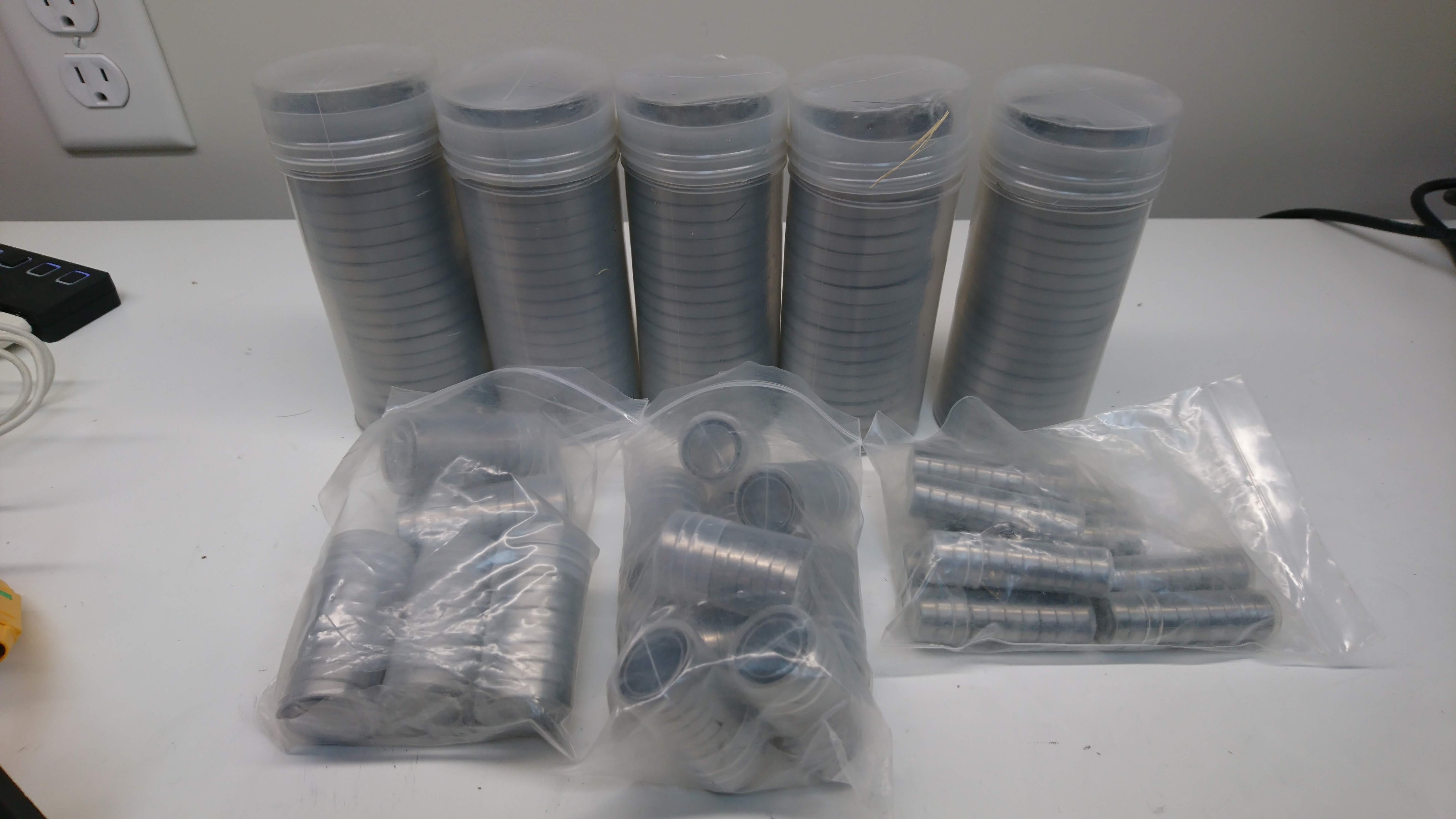
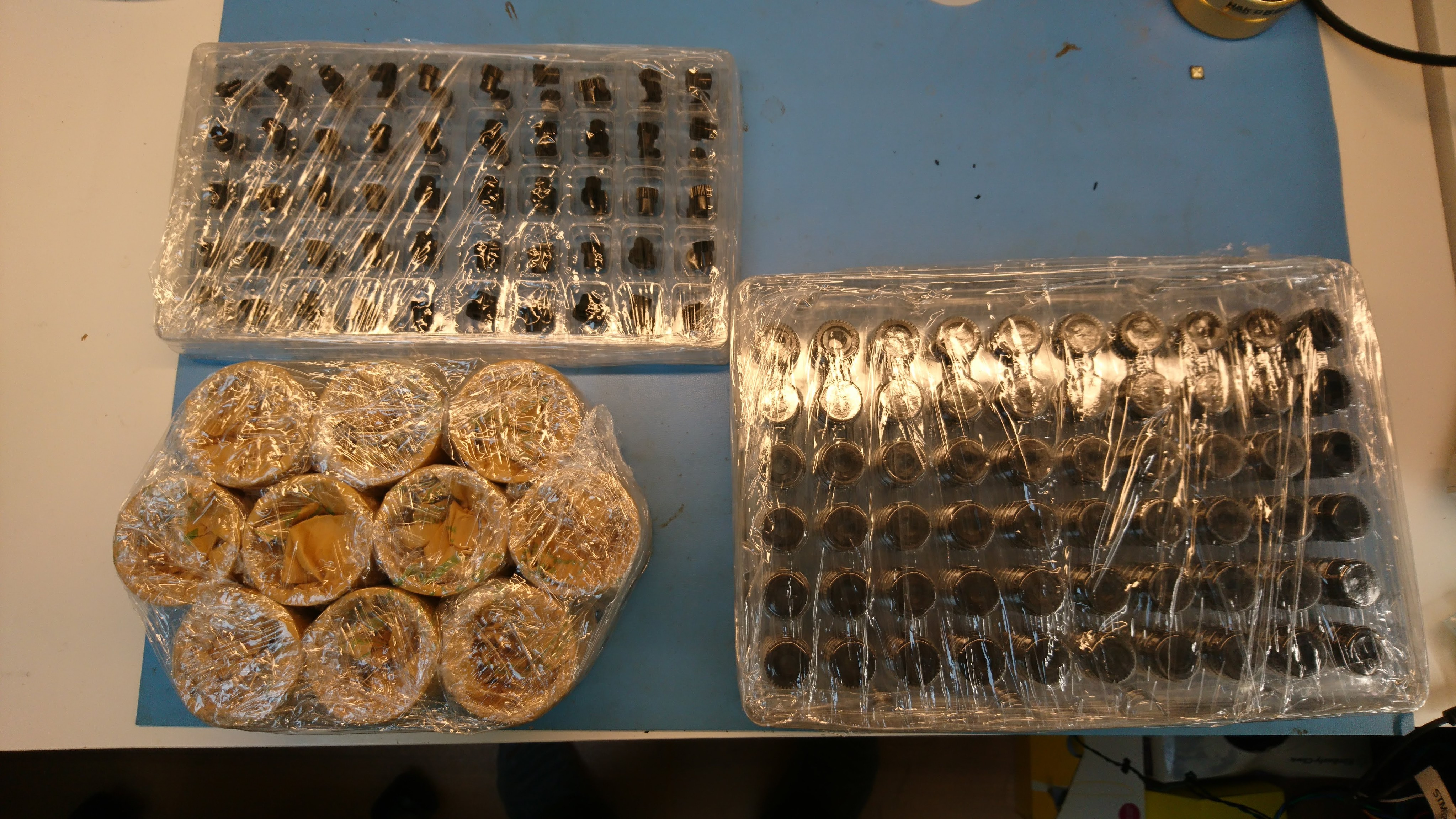
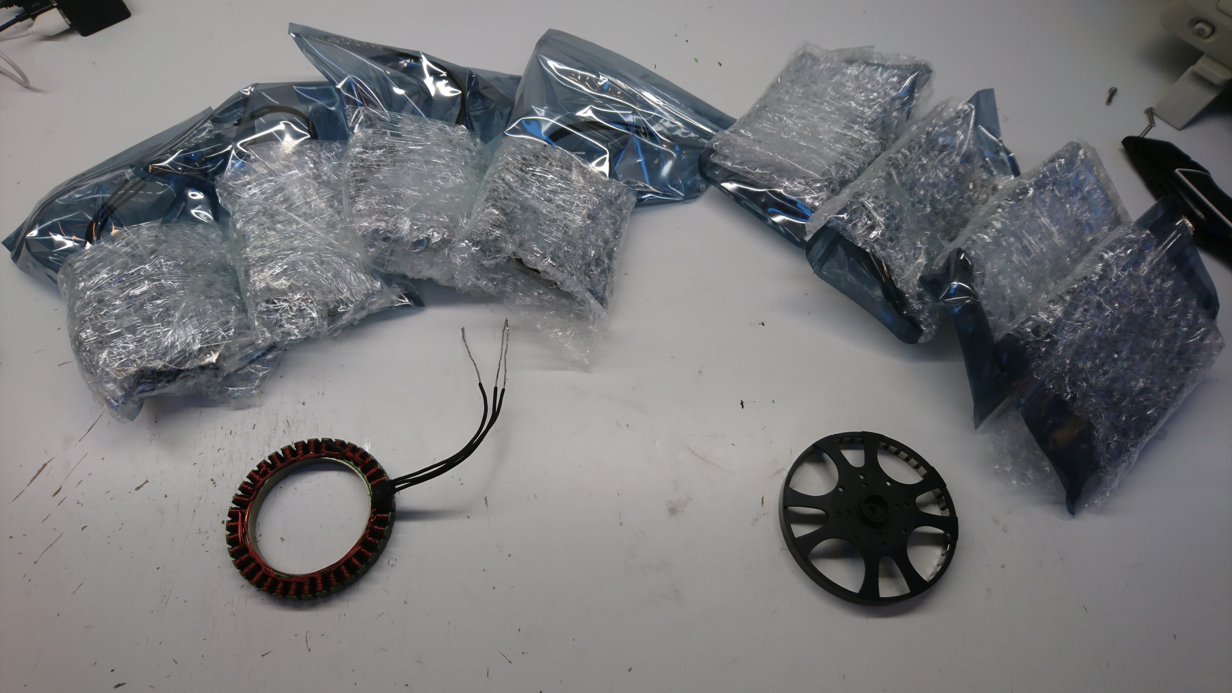
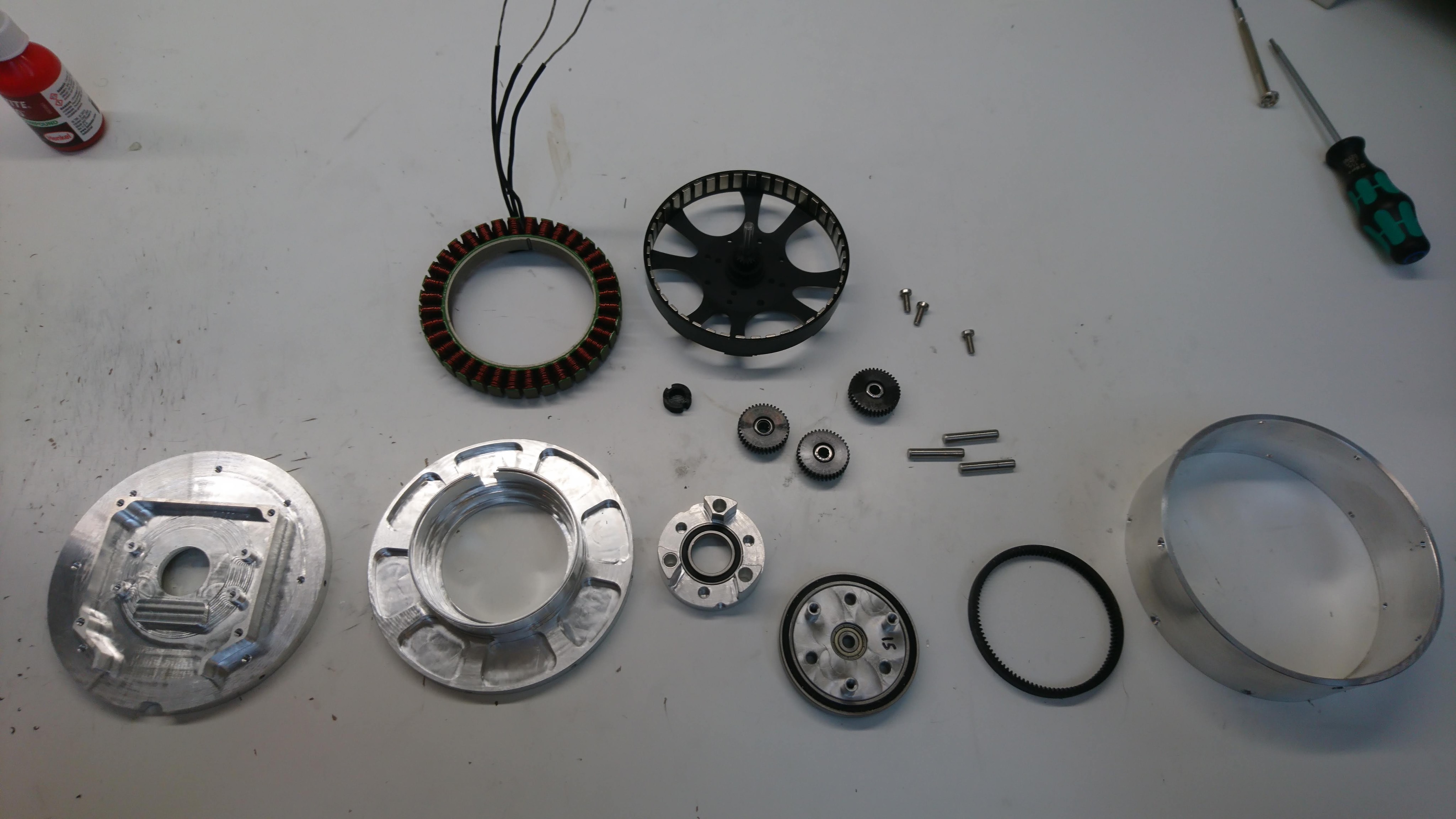
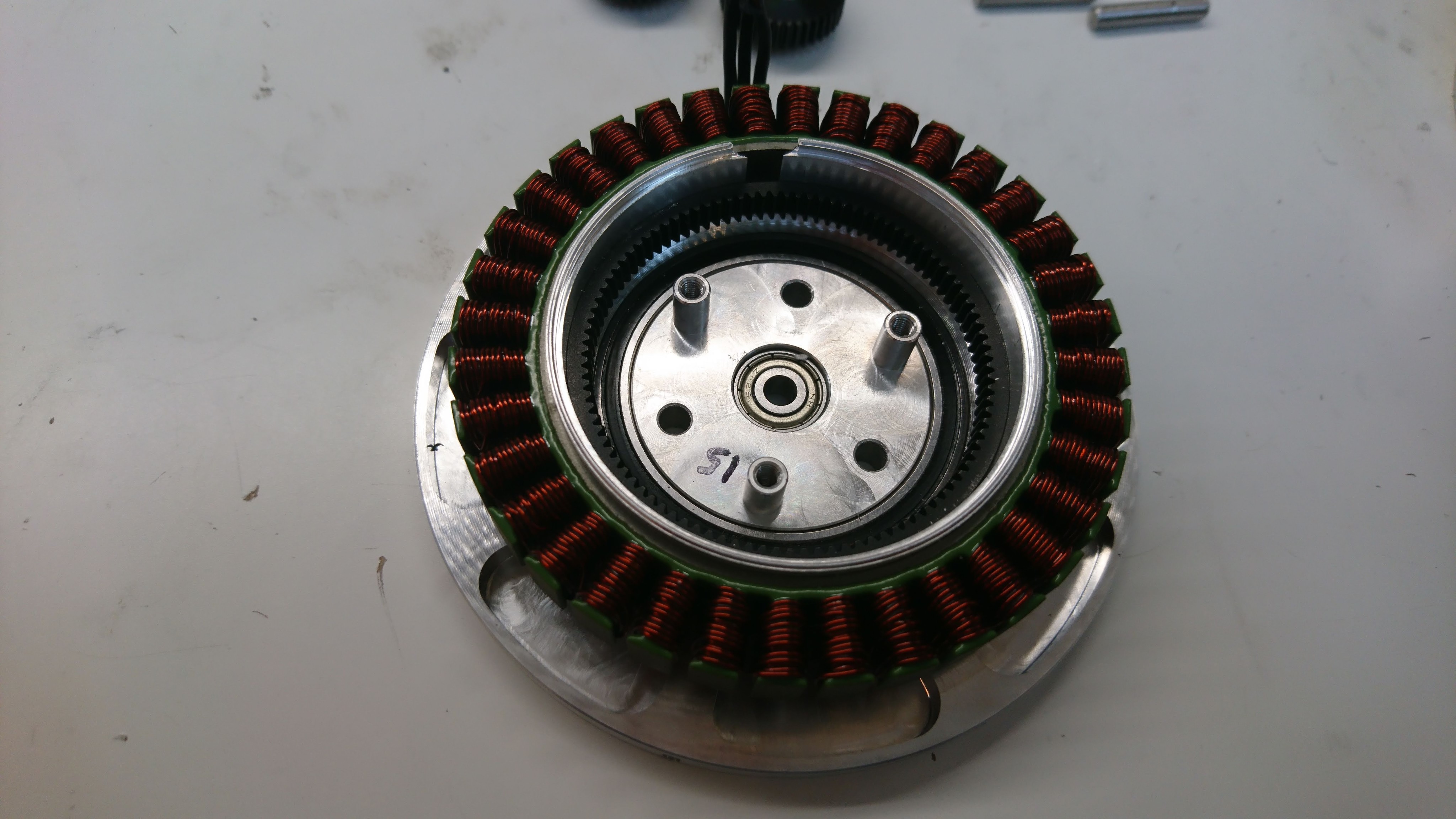
Some time ago I put in orders for all the long lead time items on a second version of the moteus servo.  This is primarily aimed at improving the manufacturability and reliability, along with some minor performance improvements.  I’ve now got at least samples of all the long lead time parts in house!

Loads of bearings

Loads of bearings

A lot of custom gears

A lot of custom gears

A sample batch of custom rotors and stators

A sample batch of custom rotors and stators

Successful pronking!

While not perfect, now that I have flux braking in place, I have now succesfully pronked around for a while without faulting!  There are a number of outstanding problems that still need to be addressed:

  • Sometimes the landing phase is erroneously cut short
  • There is occasionally a grinding like noise that sounds like some controller is unstable
  • I think the lateral movement is not working correctly
  • The gait needs to be smarter about moving the legs past the center point when in mid-flight, and changing the gait period to achieve different speeds
  • And probably a bunch of other problems I haven’t even identified yet

That said, it is still fun to watch it romp around!

quad A0 chassis v2 - final assembly

In the last post in this series, I conducted a fit test on the new chassis.  After my ignominious belly-flop, I now had a more urgent need to complete the switch.

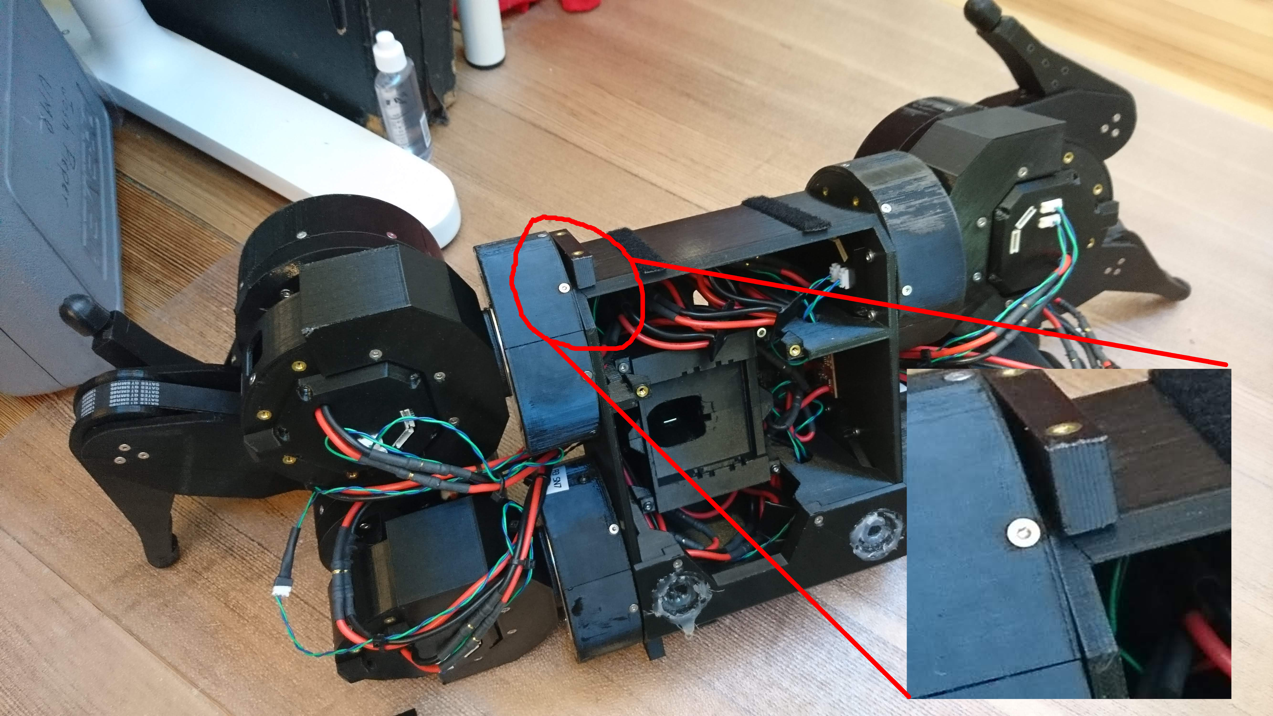
A busted robot

A busted robot

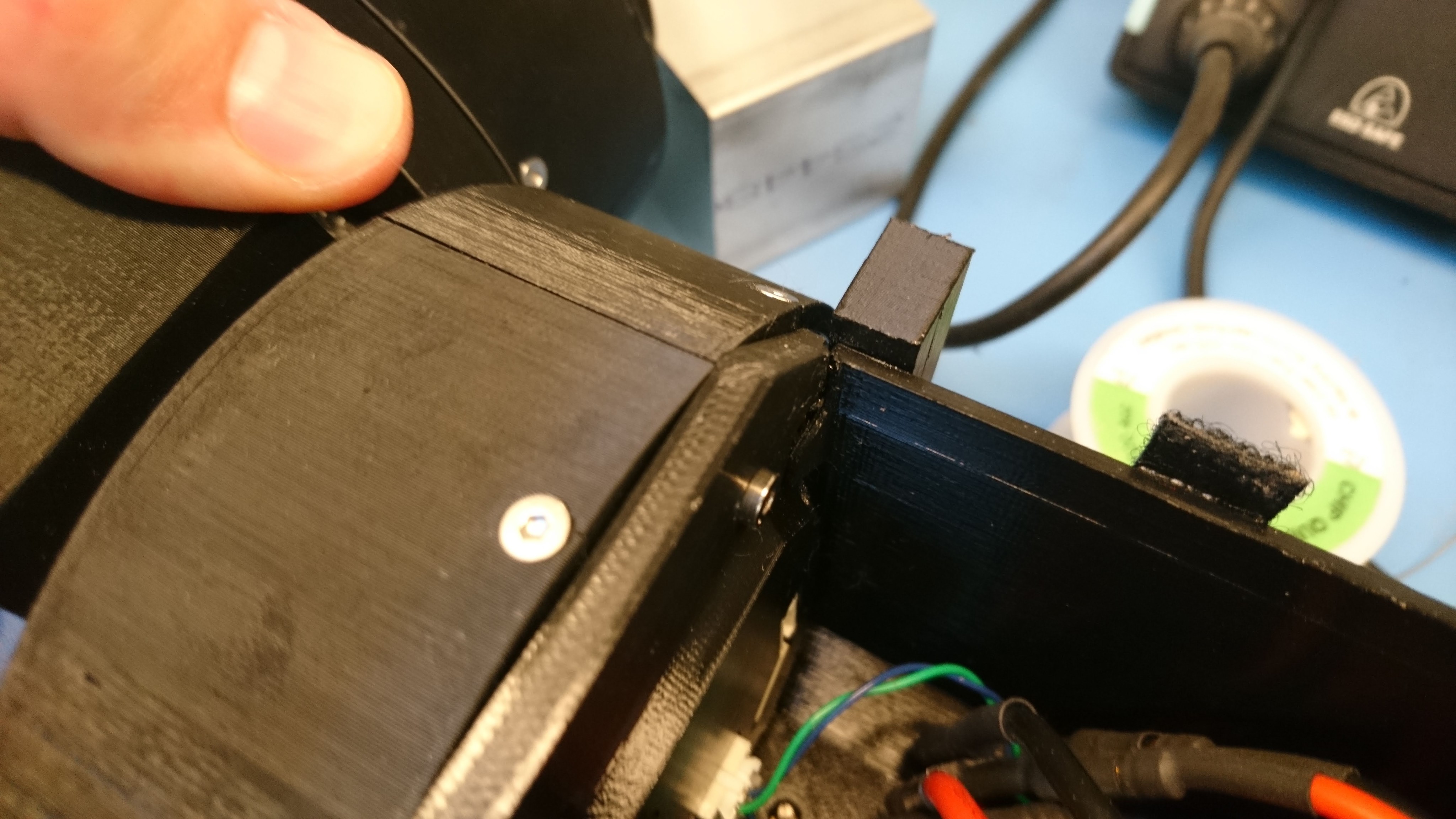
An even bigger close-up

An even bigger close-up

The chassis cracked in the corner, completely separating.  Doing anything more with this chassis was likely to result in many more things breaking very quickly.

Build process

So, here are the photos as I put everything together.