Archives: 2019

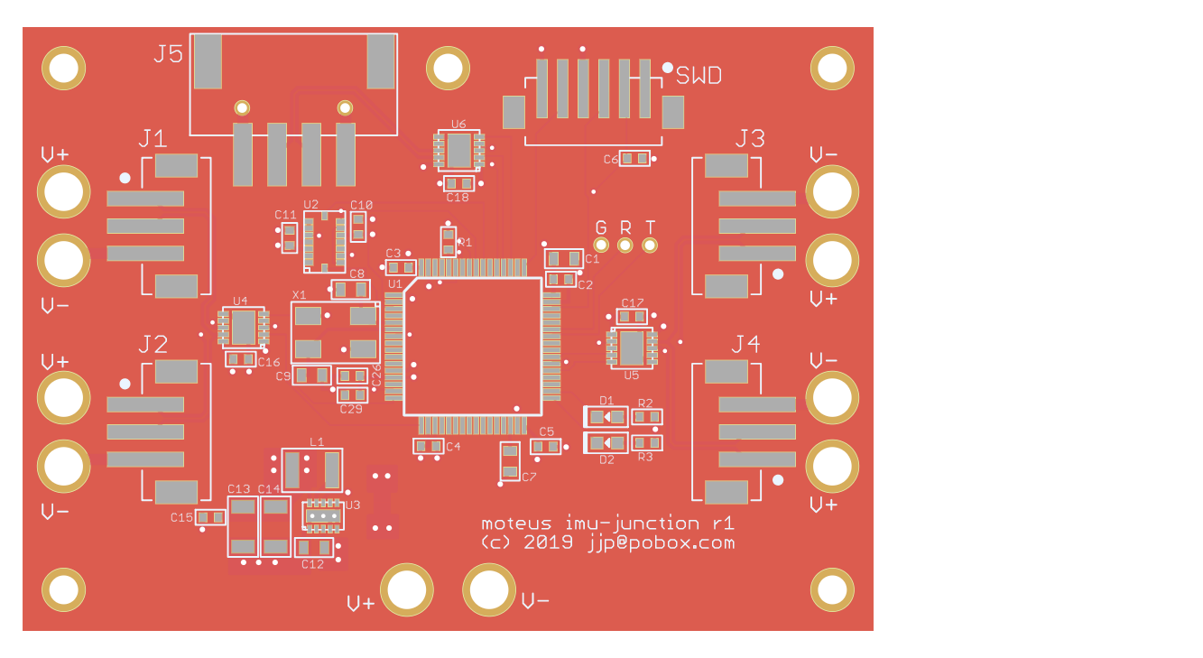
Quadruped Junction Board

The full quadruped robot needs to both distribute power from the primary battery and RS485 serial network to all 12 servos.  To make the wiring of that easier, I’ve made up a junction board to provide power connectors, distribute the data network, and act as the IMU for when that is necessary.

20190314-moteus-imu-junction-r1.png

The RS485 network is bridged between two halves of the robot.  One connection comes in from the controlling PC and two separate links go out, one for the left side and one for the right side.  This could eventually allow the controller on the junction board to take intelligent actions itself, such as querying the force applied on all 12 servos.  It could then return the result in a single RS485 transaction to the host computer.  I am expecting that will be necessary to achieve closed loop control approaching 1kHz.

My simplest ever PCB

While wiring up the first 3 degree of freedom mammal actuator, I knew I was going to have a need to distribute power to each of the three motor controllers.  Thus, enter my simplest ever PCB.  It is just 4 holes for each of power and ground with traces connecting them.

moteus busbar PCB

moteus busbar PCB

It took an annoying amount of time to actually solder in all the necessary wires, but it was still better than the alternative of a bunch of ring terminals bolted together.

moteus brushless servo open source release

moteus is an open source brushless servo actuator designed for use in highly dynamic robots.  It consists of PCB designs, software, and mechanical designs necessary to construct powerful brushless servos, and link them together into legged robots.  Today I’ve published the full source and designs for all of this work on github under an Apache 2.0 License - https://github.com/mjbots/moteus

moteus r3 controller installed on leg

moteus r3 controller installed on leg

These are the software and designs I have been developing in order to replace the actuators on Super Mega Microbot (which will probably get a new name shortly as well).  It isn’t done, but at least the controller is working well enough now that I have a pre-production verification run of ~30 controllers in flight.  Even still, I expect that further evolution, both on the controller board and in the mechanical systems is inevitable.

Controller r3 and endurance testing

After my self-education on MLCC derating I spun yet another low-volume prototype run of the servo controller.  This one has more than double the effective capacitance by doubling the number of capacitors and by selecting capacitors that have less derating.  I also fixed an incorrect pad geometry for the 6 pin ZH connector, optimized the BOM count a bit and reselected parts that were no longer available.

2x fully assembled controller r3

2x fully assembled controller r3

Mammal geometry leg revision

After getting the first version of the mammal geometry leg working and jumping I worked on a second revision.  At a minimum, I wanted to fix all the problems that required hand machining, however I also decided it was trivial enough to add a reduction ratio to the tibia through the belt drive, that I should just go ahead and do it.  My inverse kinematics calculations showed that this would make a big difference in average power consumption.

Welcome Mini Cheetah!

It is great to see that Ben Katz was finally able to announce his work on the MIT Mini Cheetah!  I’m looking forward to reading their ICRA paper, if nothing else to figure out what motor selection they made and how to design a more compact gearing system.  My current prototypes rely exclusively on belts for reduction, as I decided that my current geared prototypes were too cumbersome.

UPDATE 2019-03-06: I now see that Ben’s thesis in his post is actually his master’s thesis, which fully describes the actuators and robots.  I had erroneously thought it was just his undergrad thesis.  Thanks for publishing so much!

New machine day - Prusa i3 MK3S

While designing the improved actuators for SMMB I’ve given Shapeways a lot of business.  I can definitely recommend it, their selective laser sintering (SLS) parts are easy to order, their website gives plenty of control, and you can expedite things to your hearts content.

That said, with the amount of 3d printing I am doing, I could have already paid for a fused deposition modeling printer several times over.  Thus, I recently acquired a Prusa i3 MK3S.  It certainly can’t print everything that you can do with an SLS process, but with slightly tweaks to the models it can do a lot of it.  The biggest upsides of course are the lower per-part costs… something like 20-100x cheaper, and the faster turnaround time.  Nearly anything I care about I can have a draft of overnight.

Motor controller heatsinking

The controllers for the improved actuators for SMMB have a moderate amount of power to deal with.  During jump maneuvers they can put 60 amps of phase current into the motor, and I’ve applied for very short intervals over 500W of power to a motor.  The FETs on the board are relatively high performance, but there is still a fair amount of heat that has to be dissipated.

When getting started, I knew I would likely have to do something to get heat out of the board and had a two stage plan.  The first was to heatsink the back of the controller board and second, if that wasn’t enough, heat sink the front of the board.

Mammal geometry 2d inverse kinematics

Now that I have a mammal geometry leg moving, I wanted to get a better feel for what the overall performance would be in various gaits.  I had already derived position based inverse kinematics for Super Mega Microbot, but had no such derivation for force.  Here’s my jupyter notebook with derivations for both position and force (in 2D), along with average power consumption for various forms of straight walking gait with my current draft motor selections.