The gearbox sprint
As mentioned last time, I needed to build a lot of gearboxes and new leg assemblies in a very short amount of time. So, I got to work.
Machining operations
I made a new fixture for holding stators to be extracted:
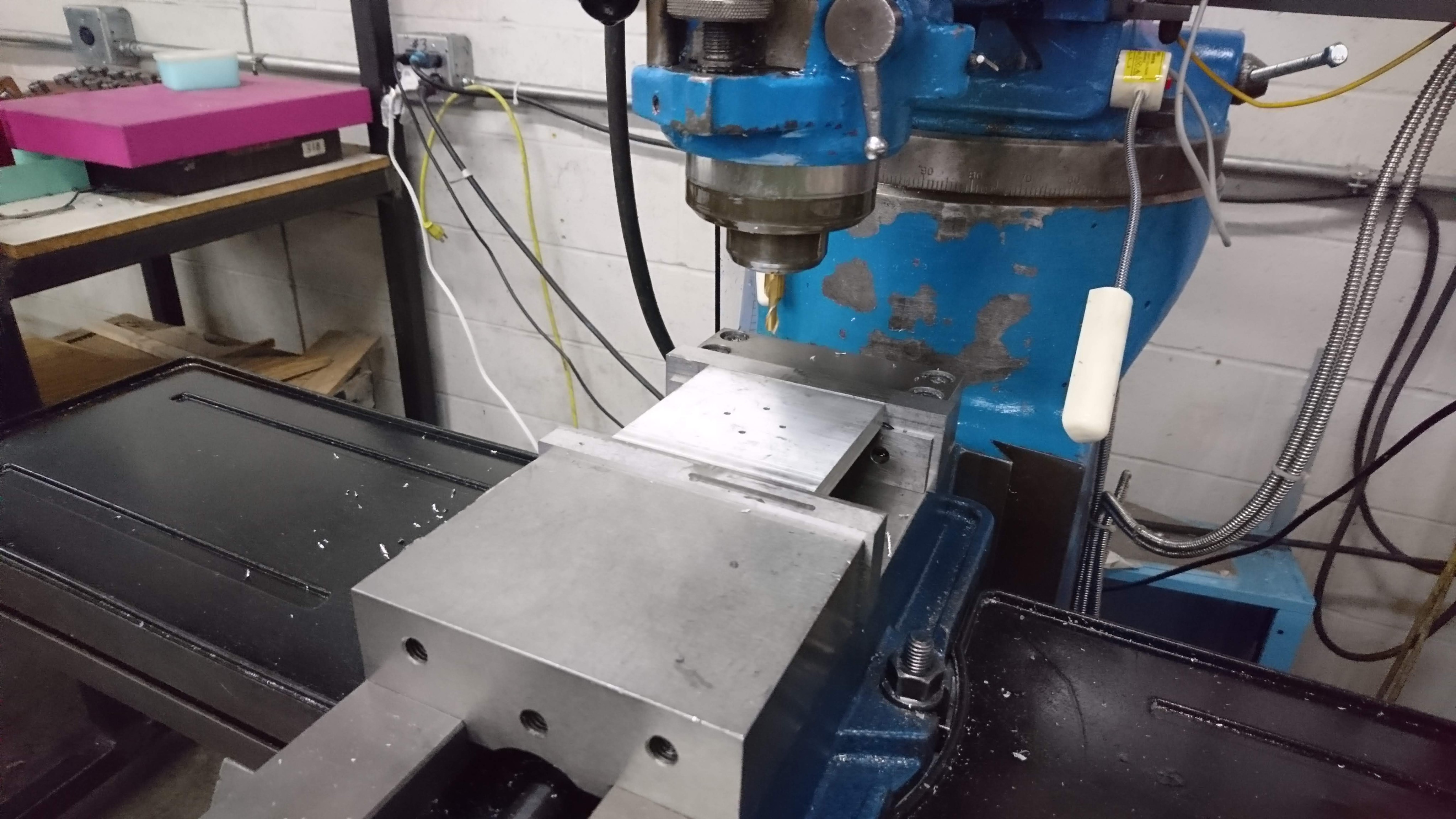
Stock in the vise
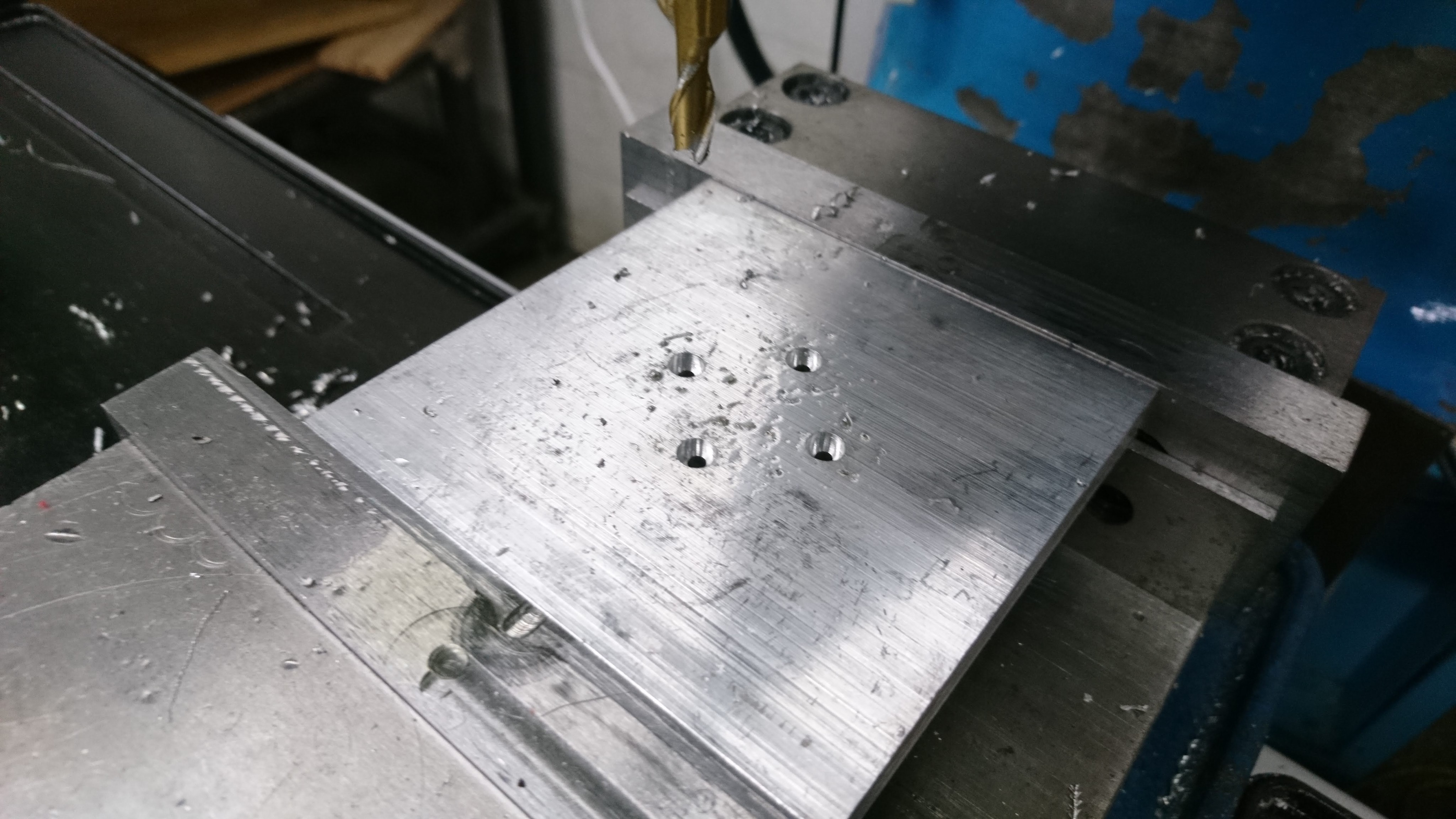
Countersinks milled
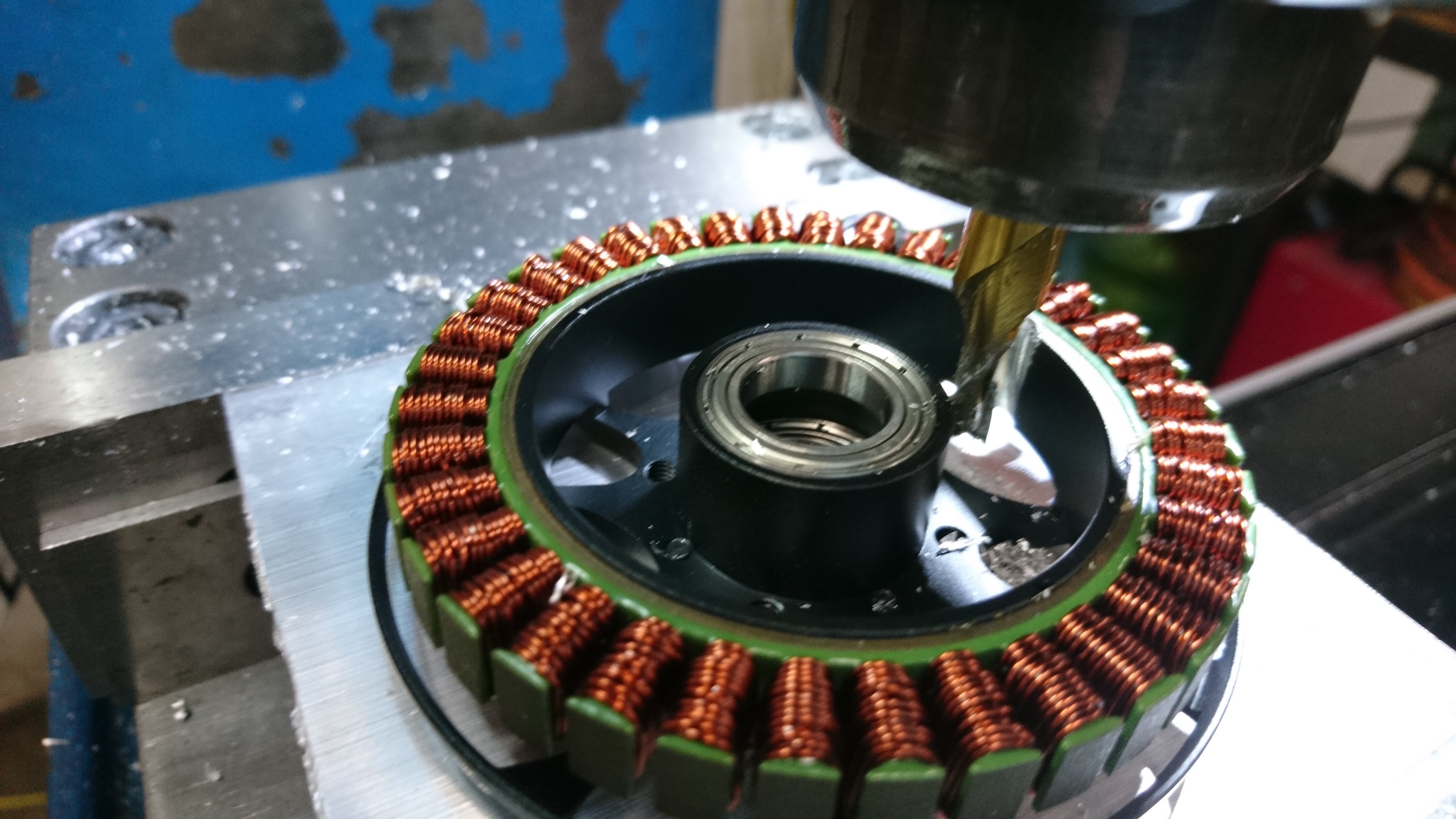
Stator mounted and fractionally machined
I turned down 8 more internal gears. To begin with, my mandrel had warped enough from the first gears that I had to add some heat set inserts to hold a cap to keep the gears on. Then on the last 2 gears, I got greedy, went too fast, and my lathe mandrel melted entirely.
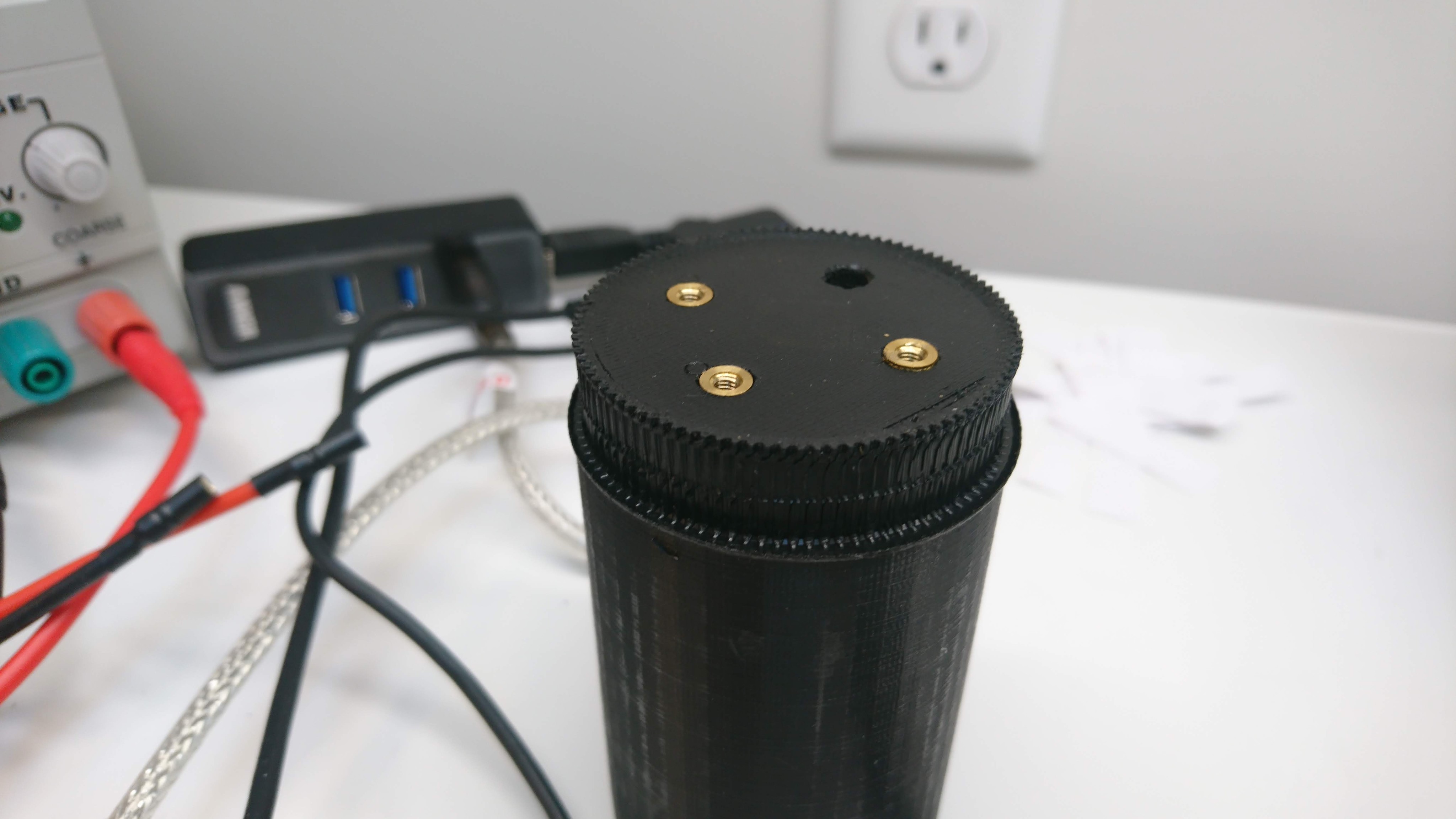
This won’t hold a gear very well :(
So, I had to spend 12 hours printing another one to finish up the last two internal gears, although their roundness was debatable after their encounter with the mangled mandrel.
I also at this point machined out a bunch more rotors, but didn’t manage to capture any photos.
Gearbox assembly
Now for some assembly:
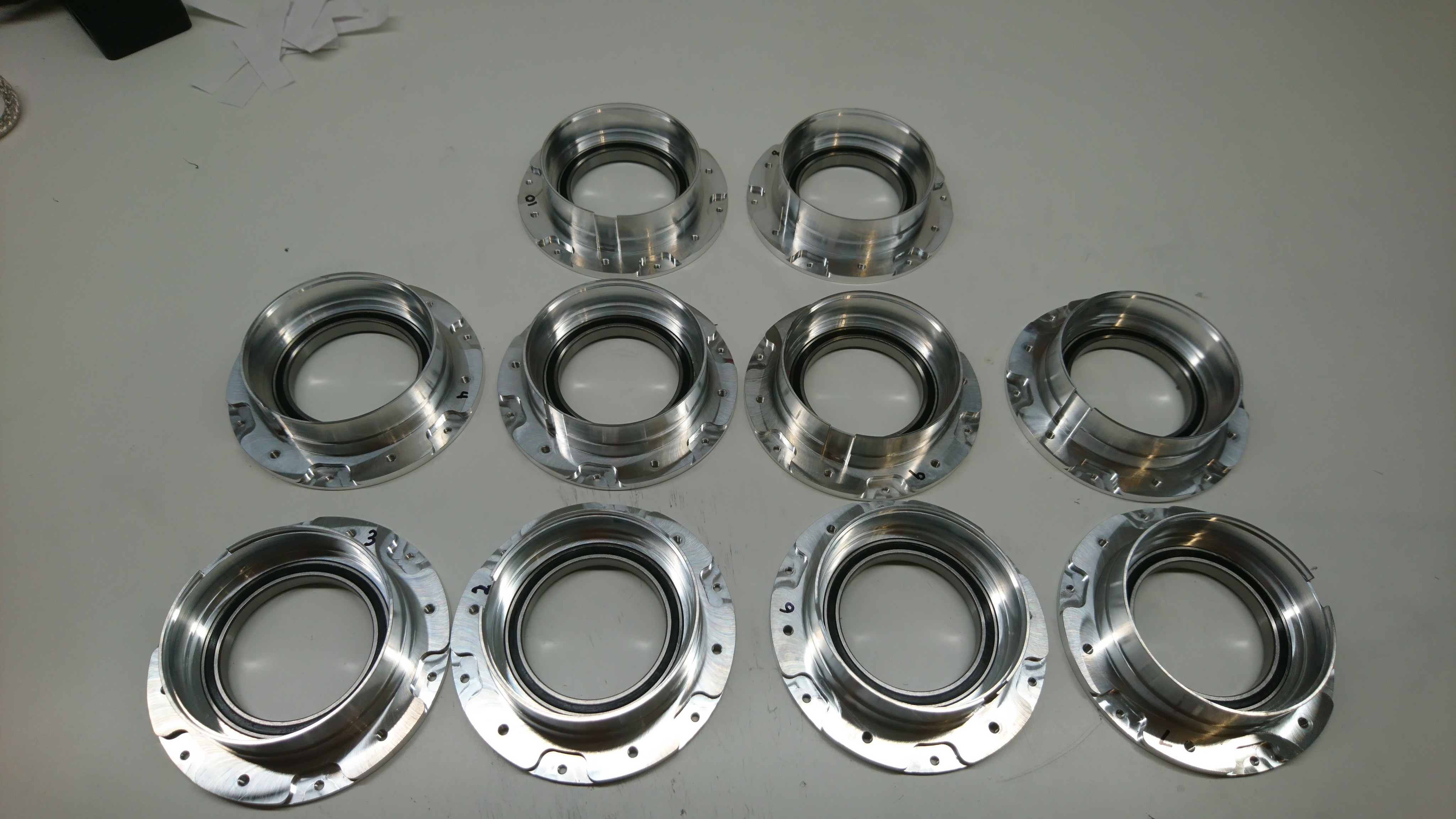
A friendly bunch of front housings
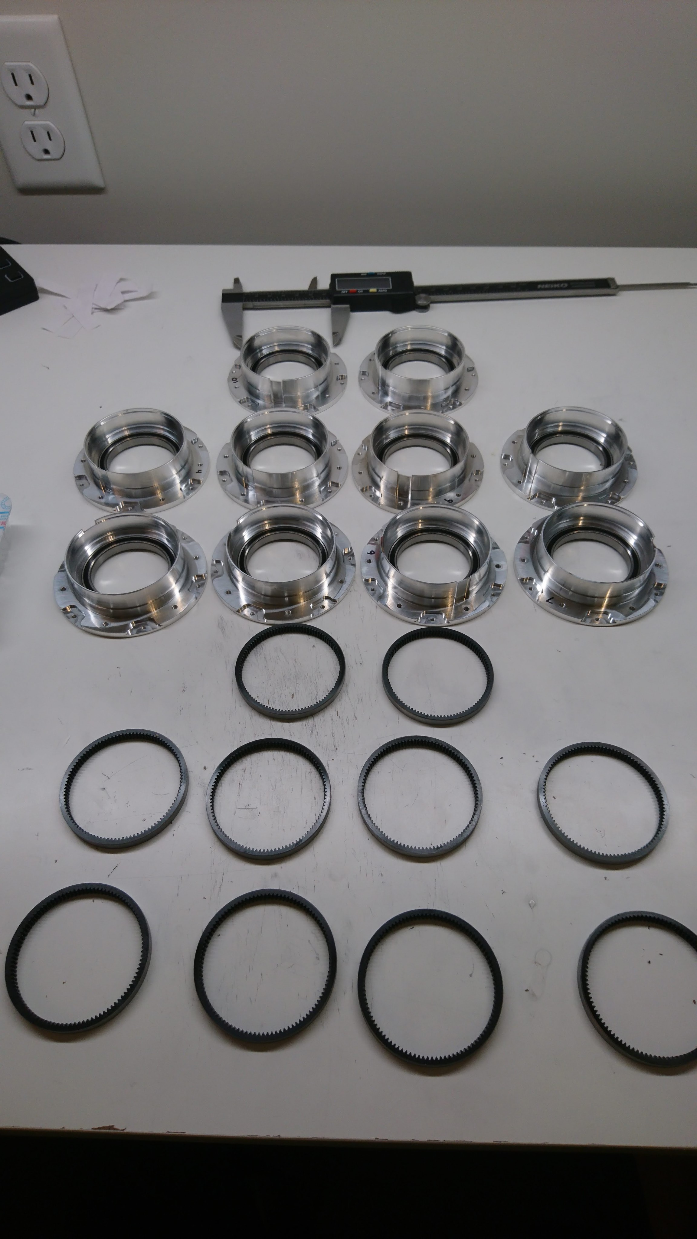
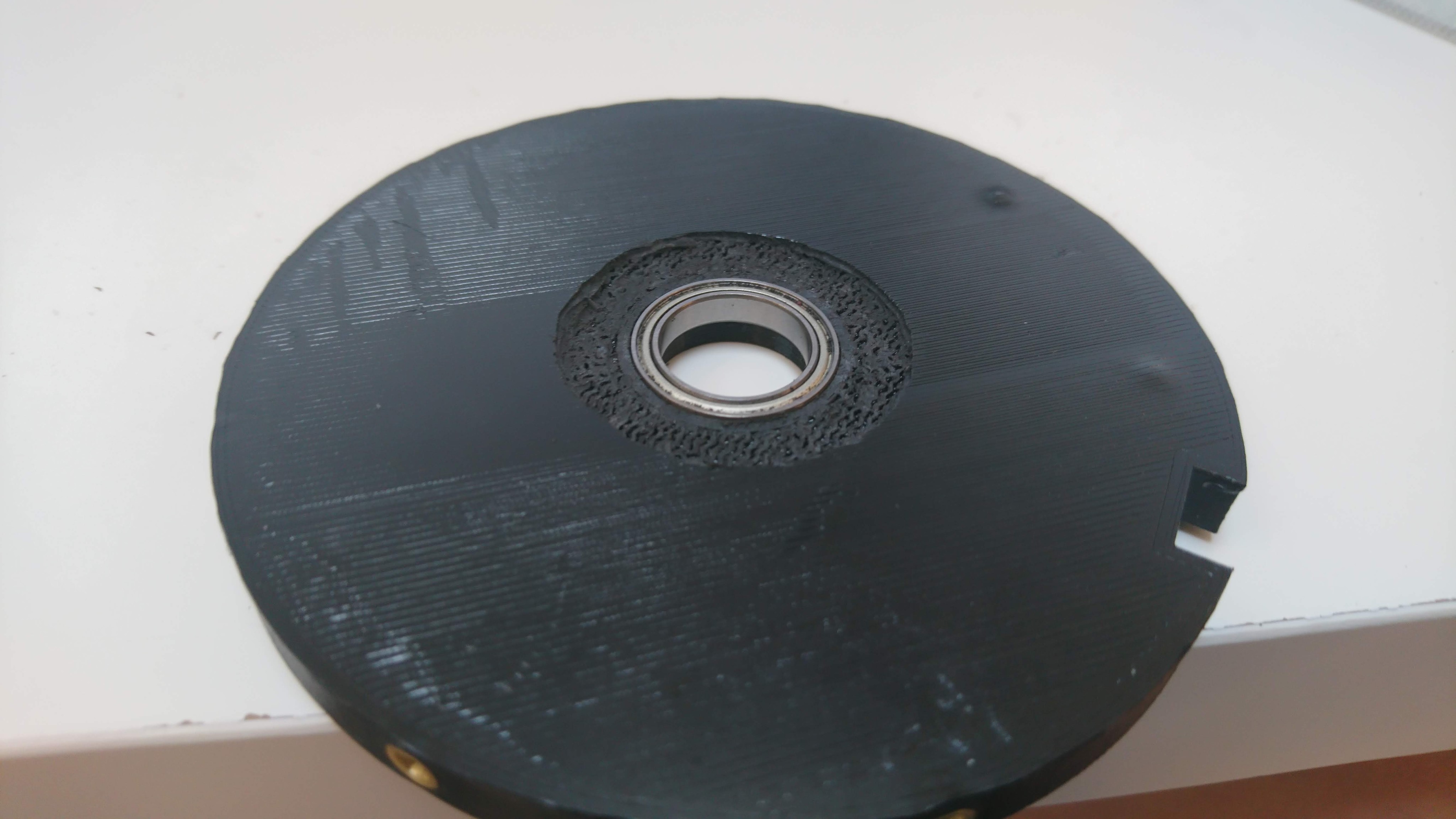
Output bearing installed, internal gears all ready
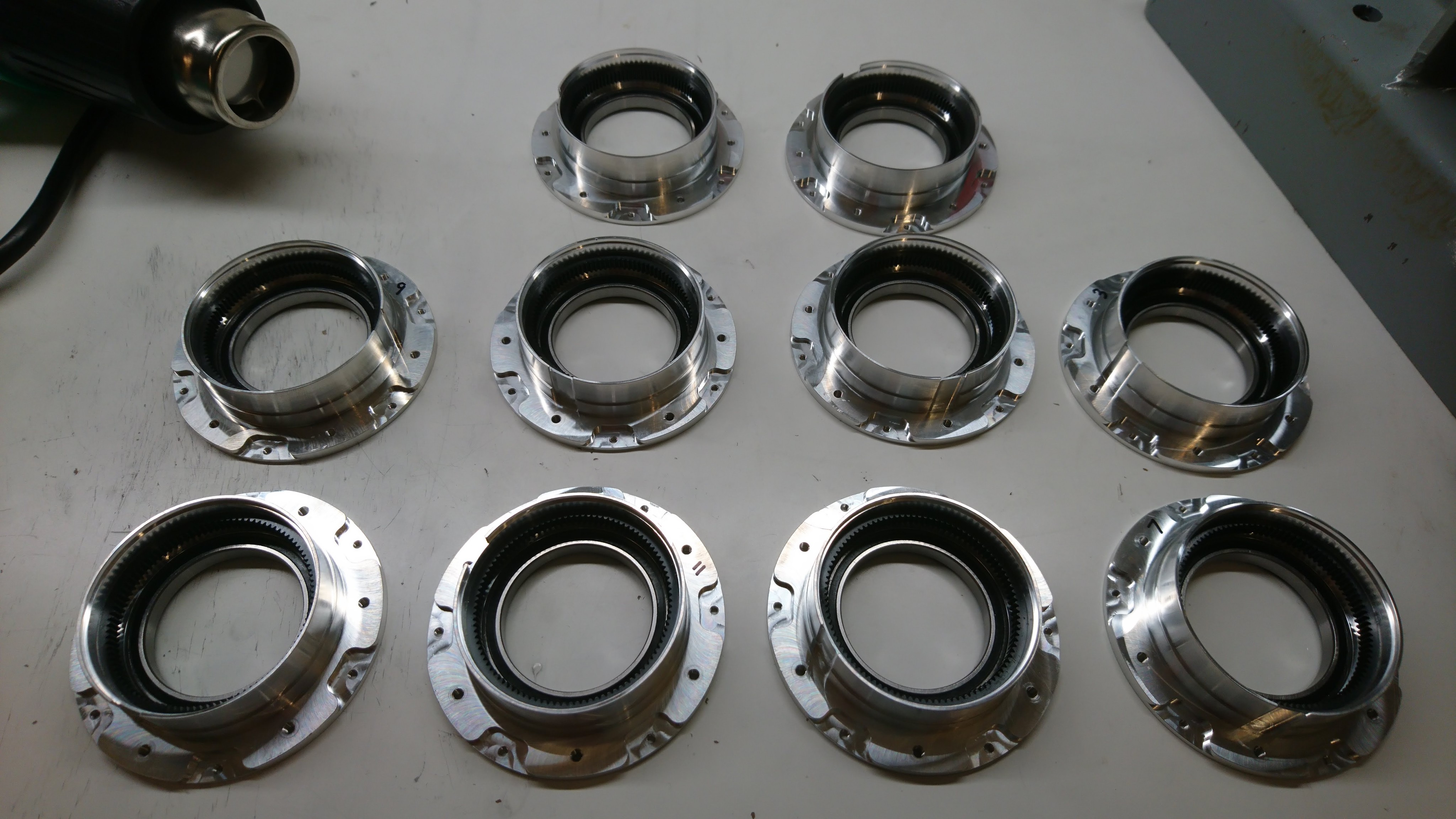
Internal gears all in place
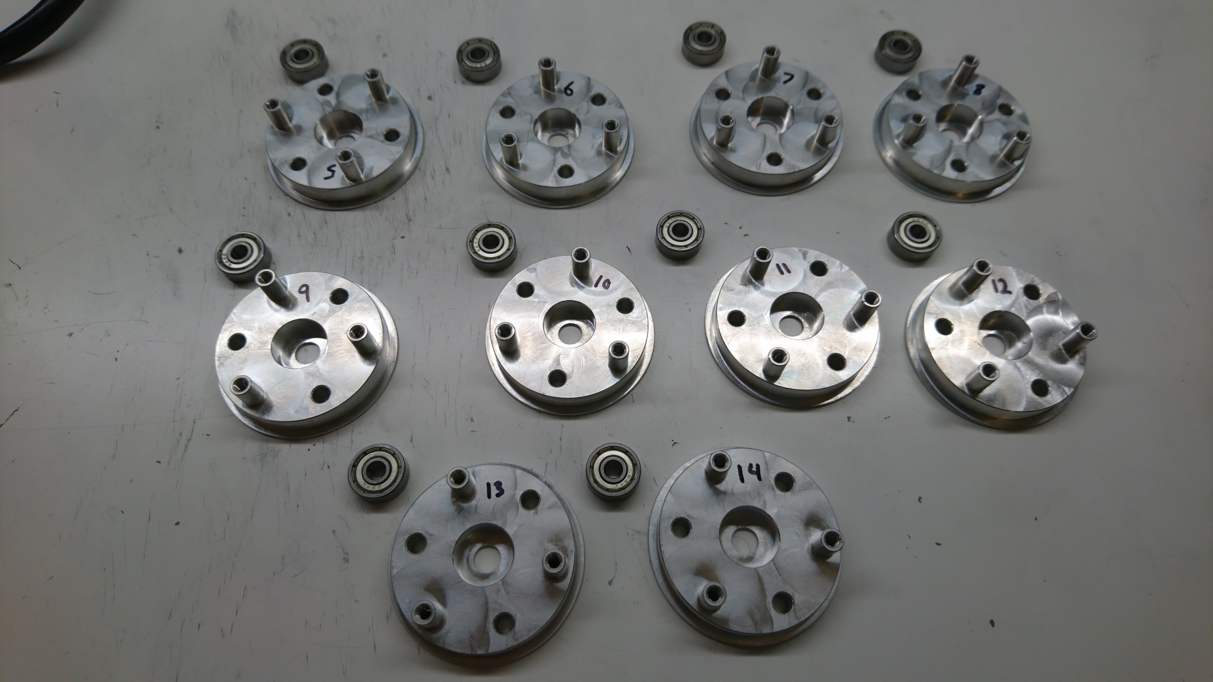
Planet outputs and output bearings
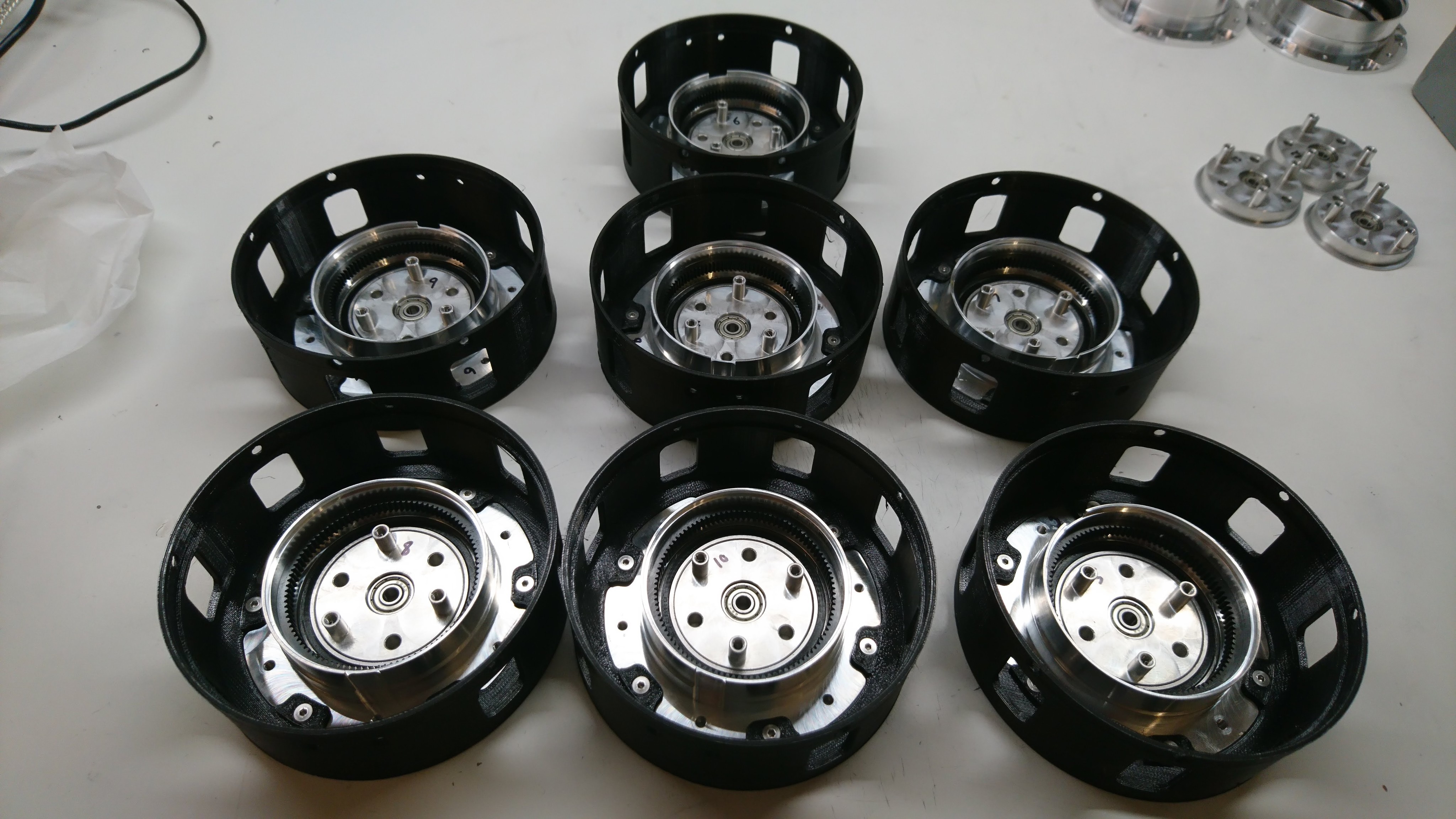
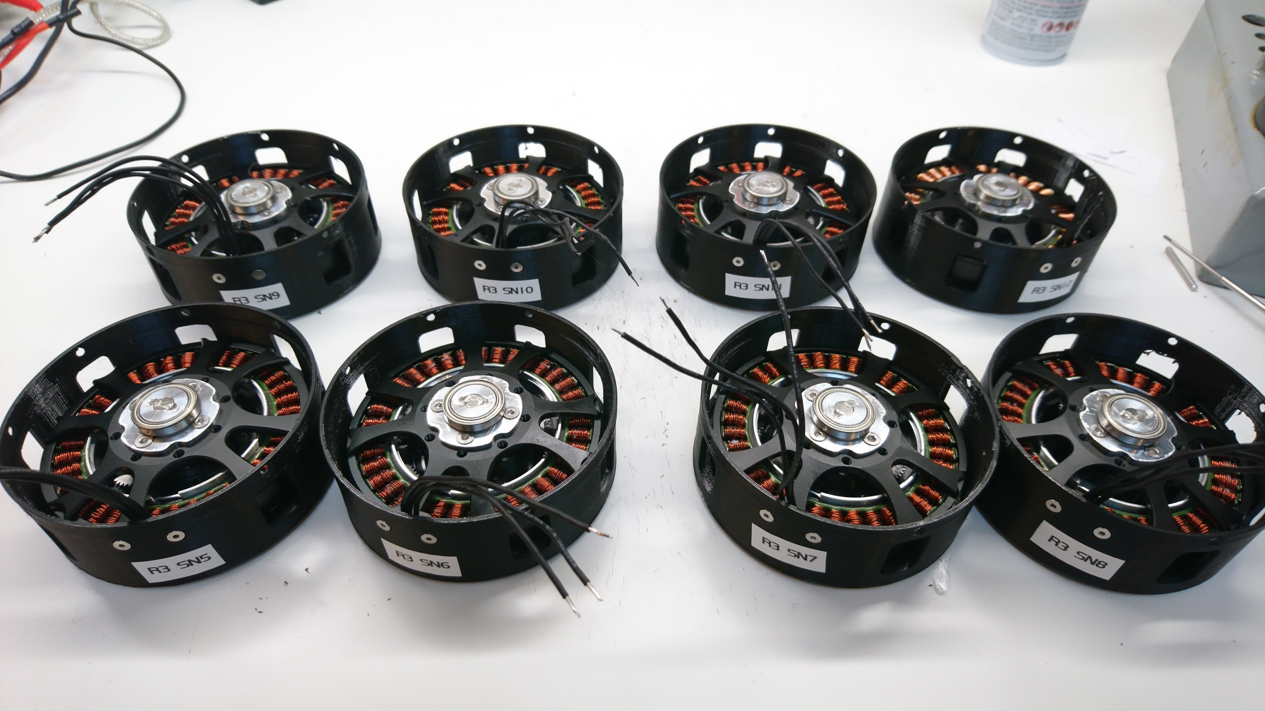
The first seven with outer housings installed
At this point I was 3d printer limited, and when I got to starting assembly, I only had 7 sets printed. Thanks to some very generous help from Beat and Roxi (thank you triply in advance!) I had a second Prusa MK3 that was also working 24/7 on the problem.
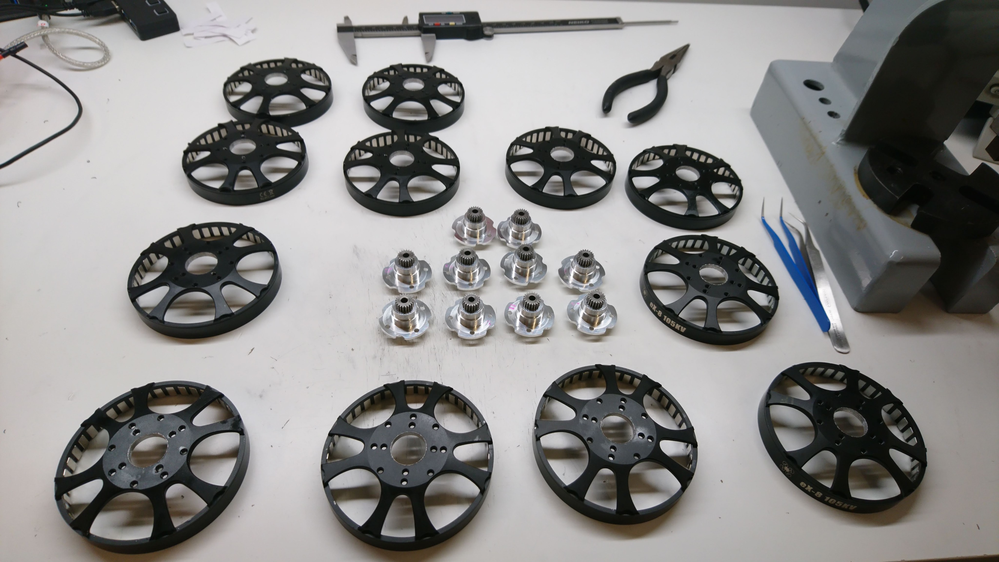
A bunch of sun gear holders and rotors
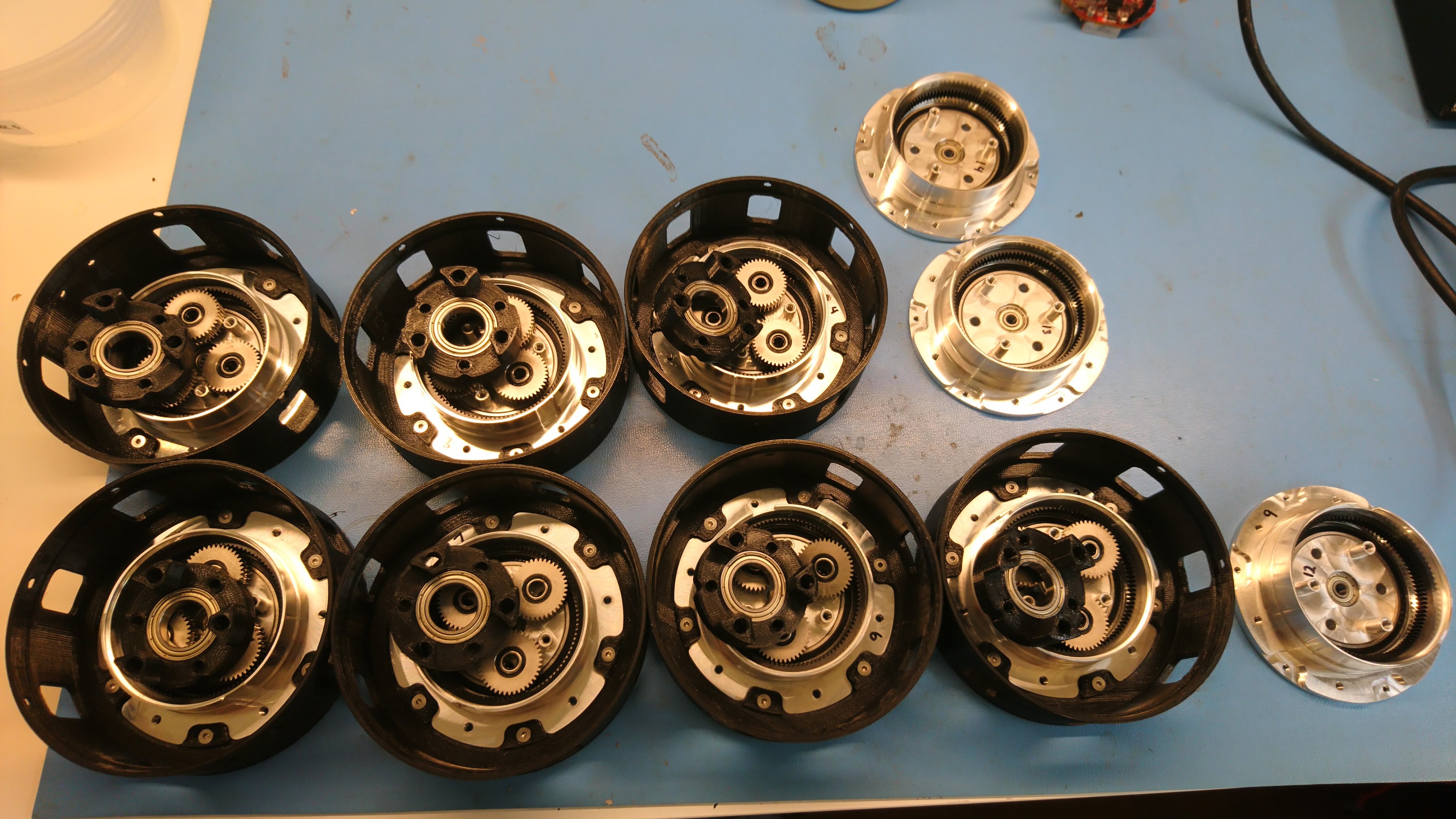
Planets installed
Planet inputs installed
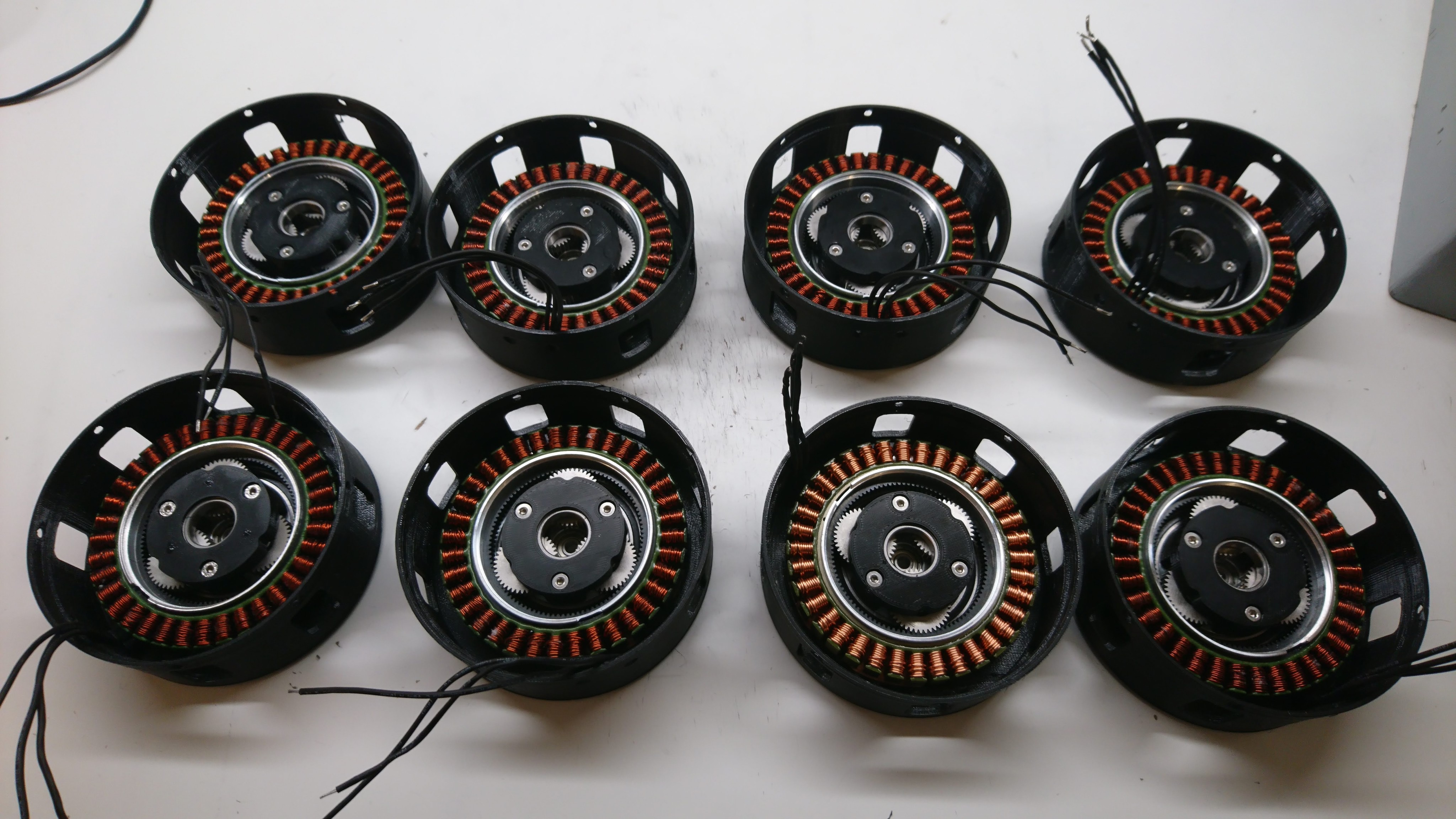
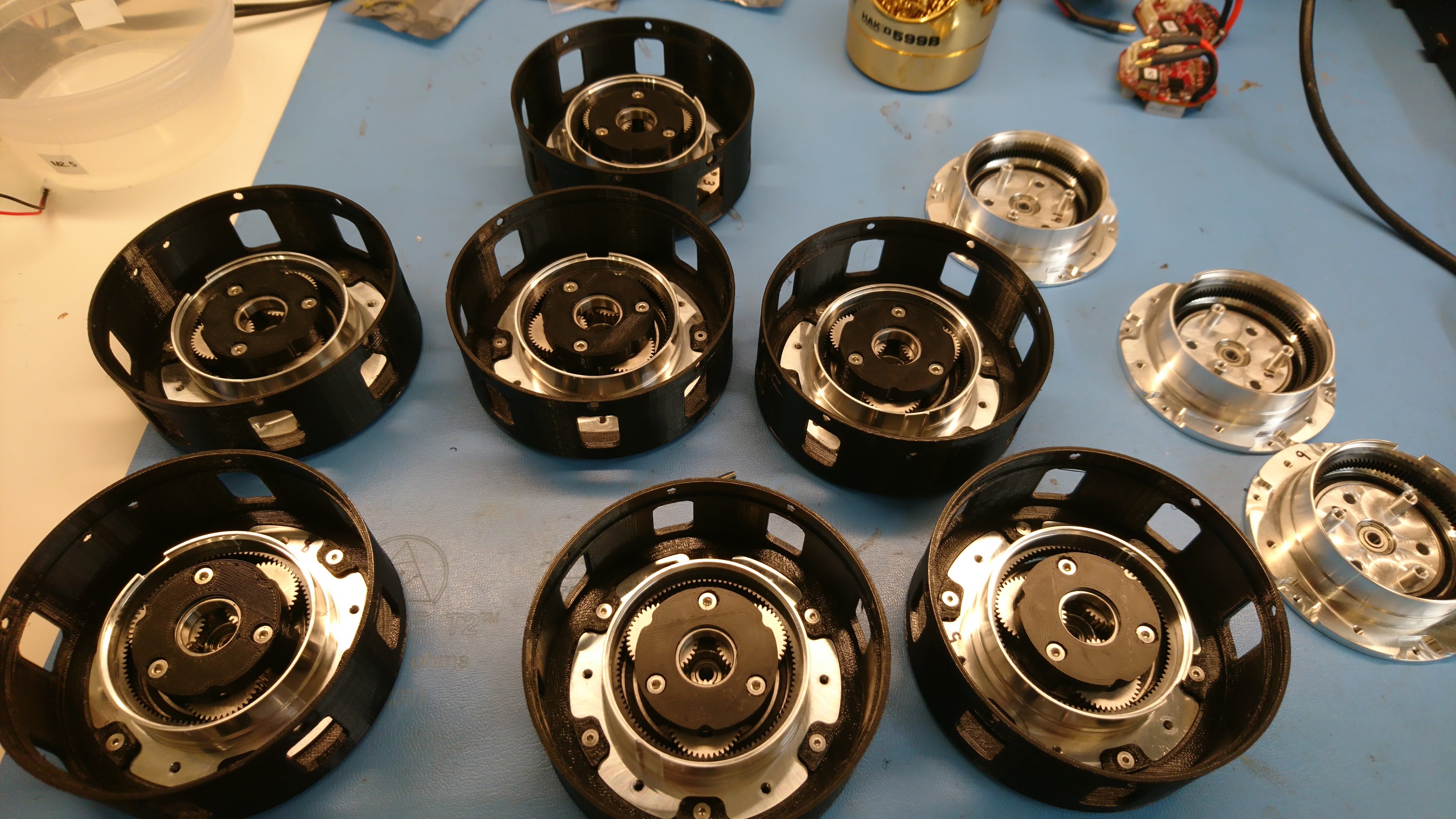
Stators installed
Notice how now I’m up to 8!
Rotors installed
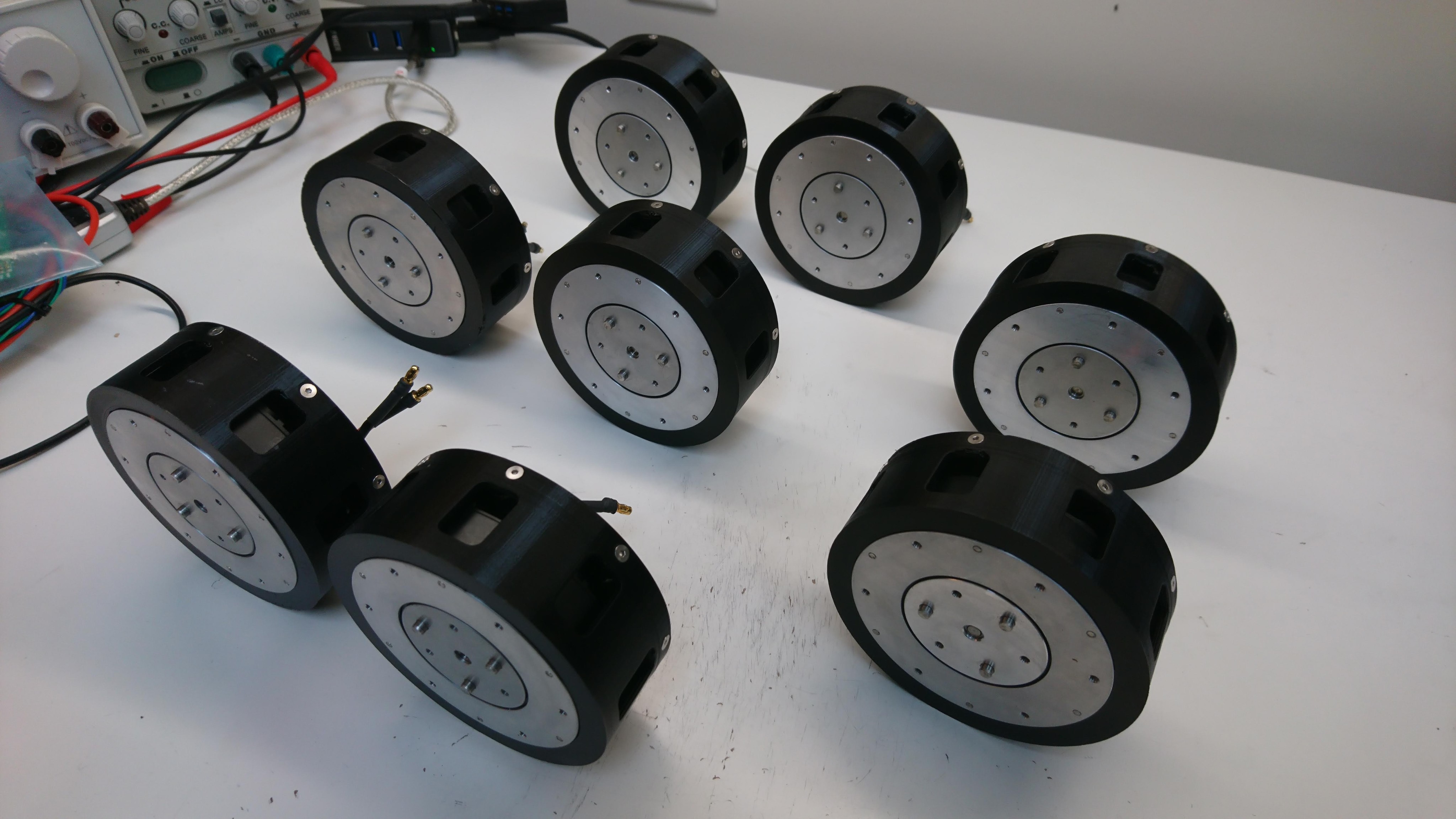
When I went to put on the backplates, I discovered that due to tolerance stackup, some of the units were having trouble fitting. To move on quickly, I post-machined all the backplates to move the rotor bearing back a bit with a dremel, and then made a little bit of clearance for the sun gear holder screws.
And then, TADA!
The legs
Now, in parallel to all that, I also designed a new leg which would mount to the gearbox output. I wouldn’t have time to get a shoulder bracket made out of metal like I had before either, so I needed to design that for 3d printing too.
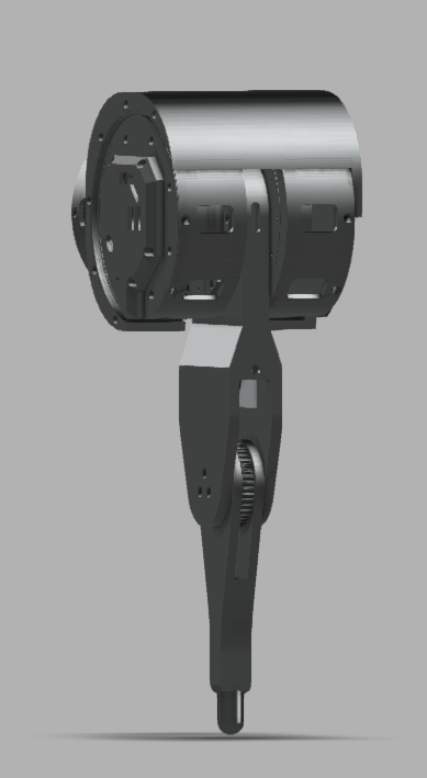
F360 rendering of leg
I made a few improvements this iteration. The biggest was that I added a tensioning mechanism inside the upper leg, so that tension could be increased after installing the lower leg. The old leg was nearly impossible to assemble without breaking it, and was just as difficult to disassemble. Also, I managed to have an actual order of assembly that was feasible and that an appropriate tool could fit in at all places at each stage of the process.
What I didn’t try to do was to try a more mini-Cheetah like geometry, or really optimize for mass or looks or anything. I was trying to get something which would likely work for the length of a Mech Warfare match in as few drafts as possible.
The design is checked into github, but is probably easier to see in the F360 web renderer: https://a360.co/4iqWbQ2
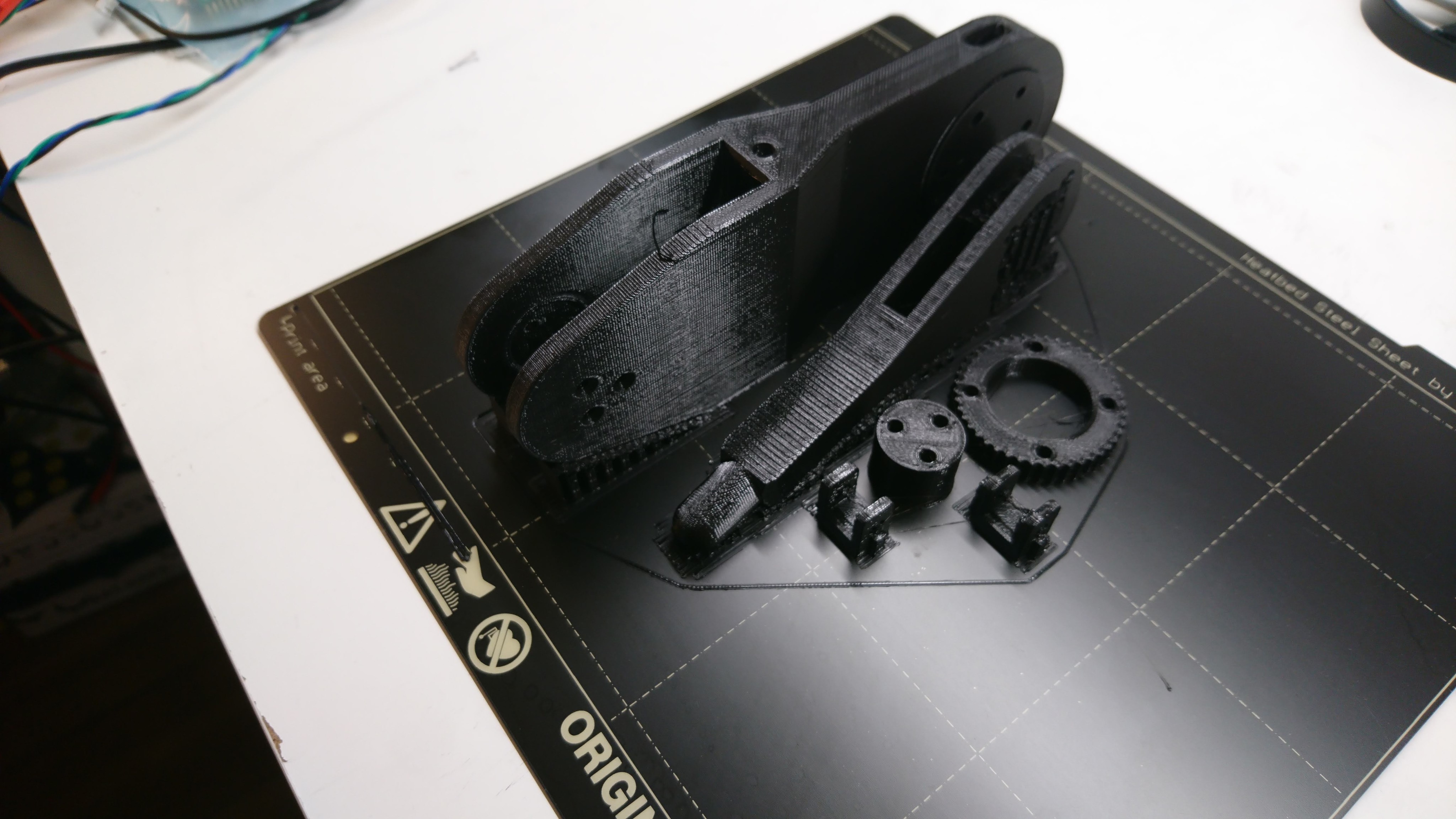
The first iteration hot off the press
Of course, the first iteration wasn’t necessarily functional. It came off the press at something like 3am Friday morning. I spent the next 4 hours machining, debugging and squeezing until I found about a dozen problems or things that needed to be fixed. Then, straight back to the printer for a second try, and voila, two was all I needed this go around!
Here is the final part-set with all metal bits installed:
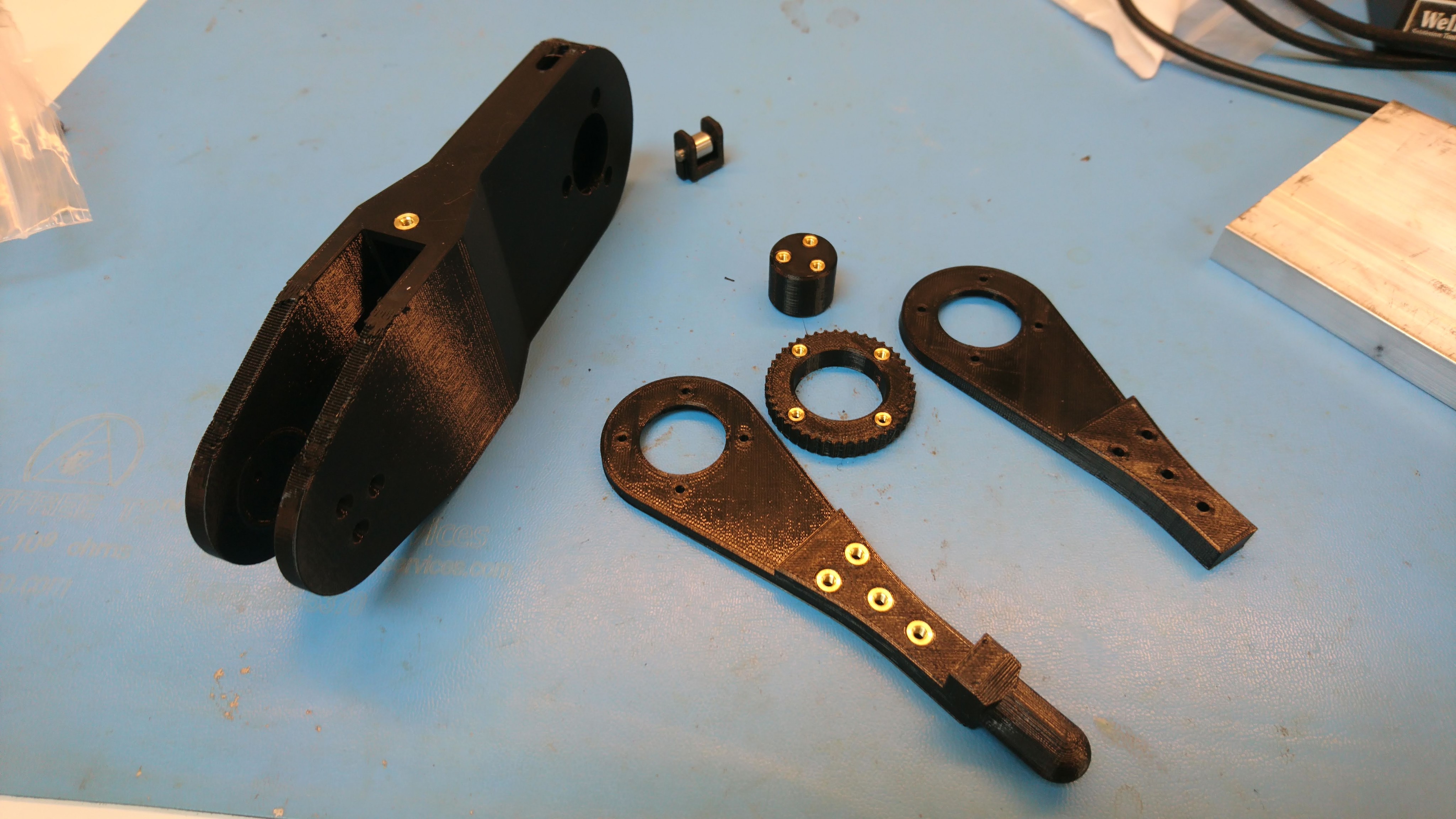
I drew and printed up the shoulder in a separate effort, but managed to capture no pictures of it whatsoever until I went to put it all together.
Leg assembly
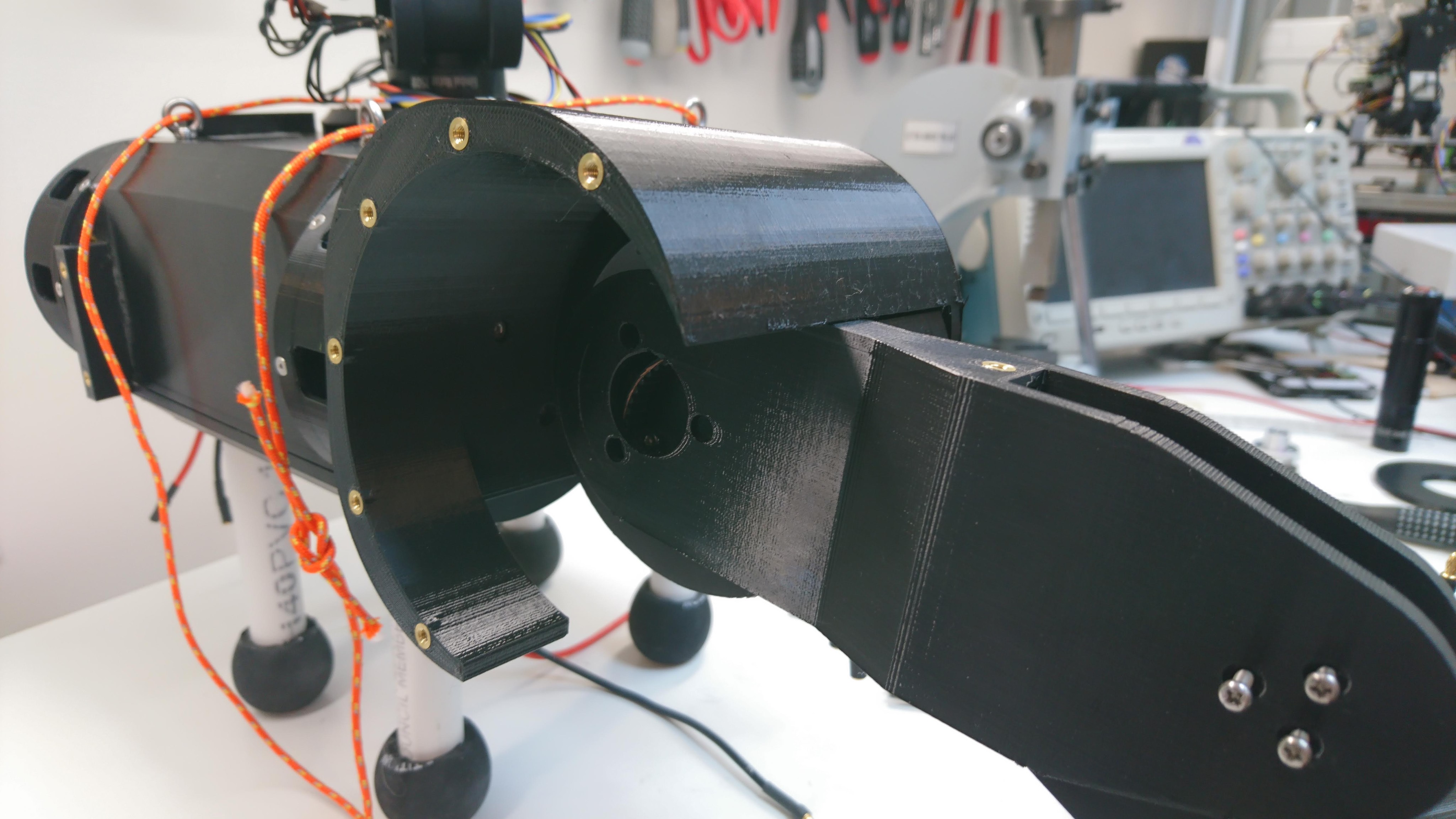
Now, here is a shoulder attached, with the upper leg motor and upper leg installed.
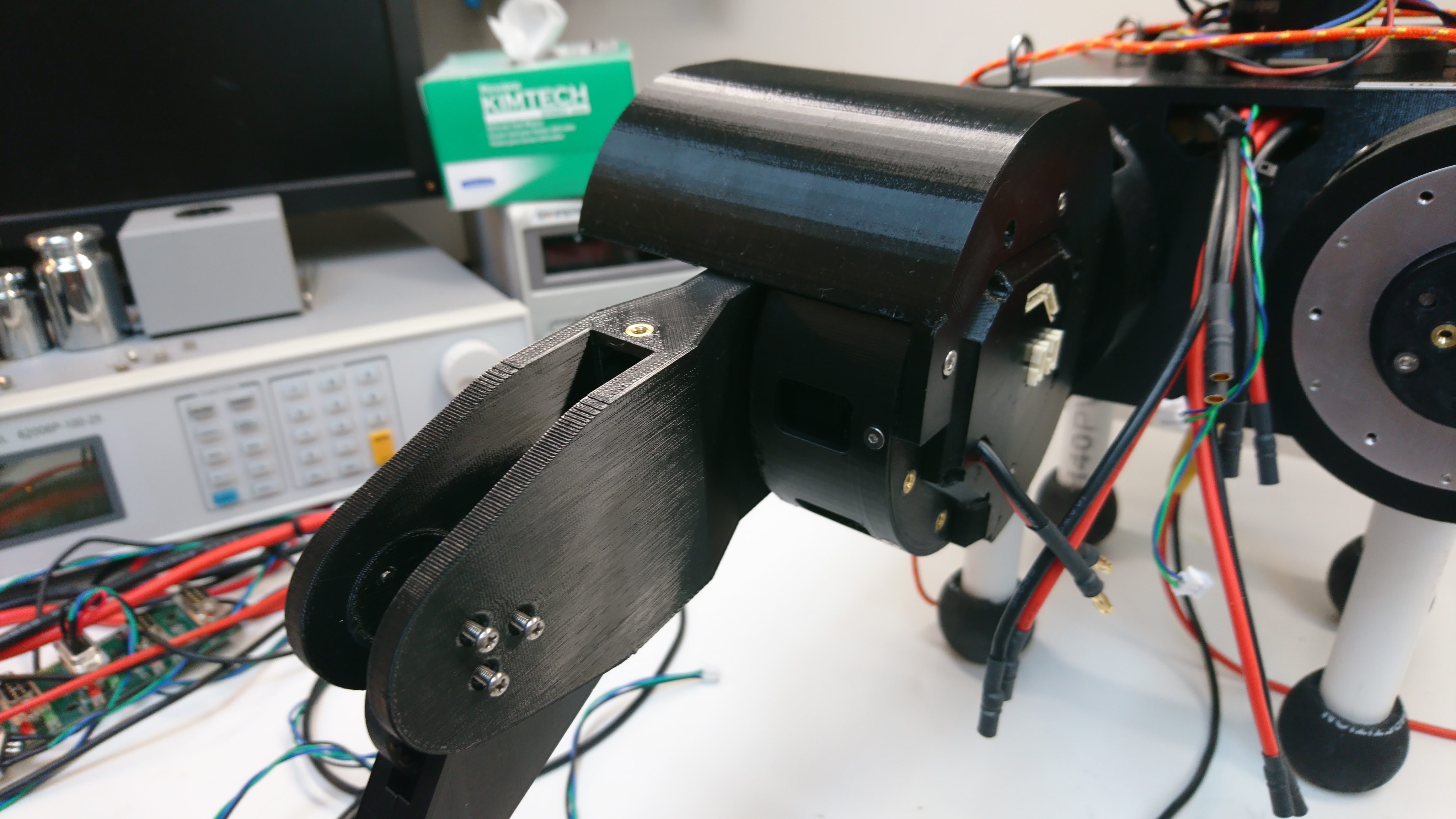
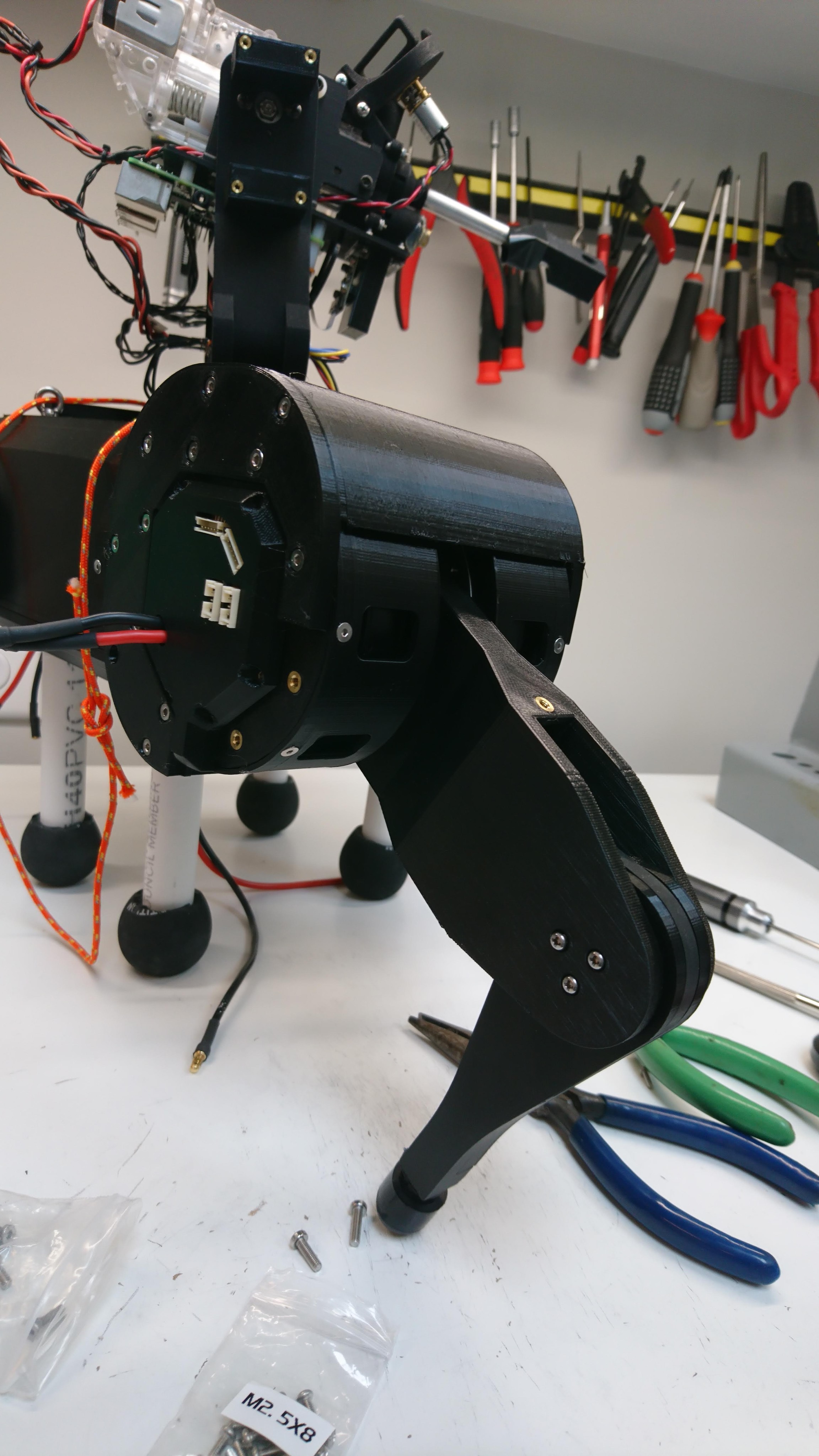
And from the other side:
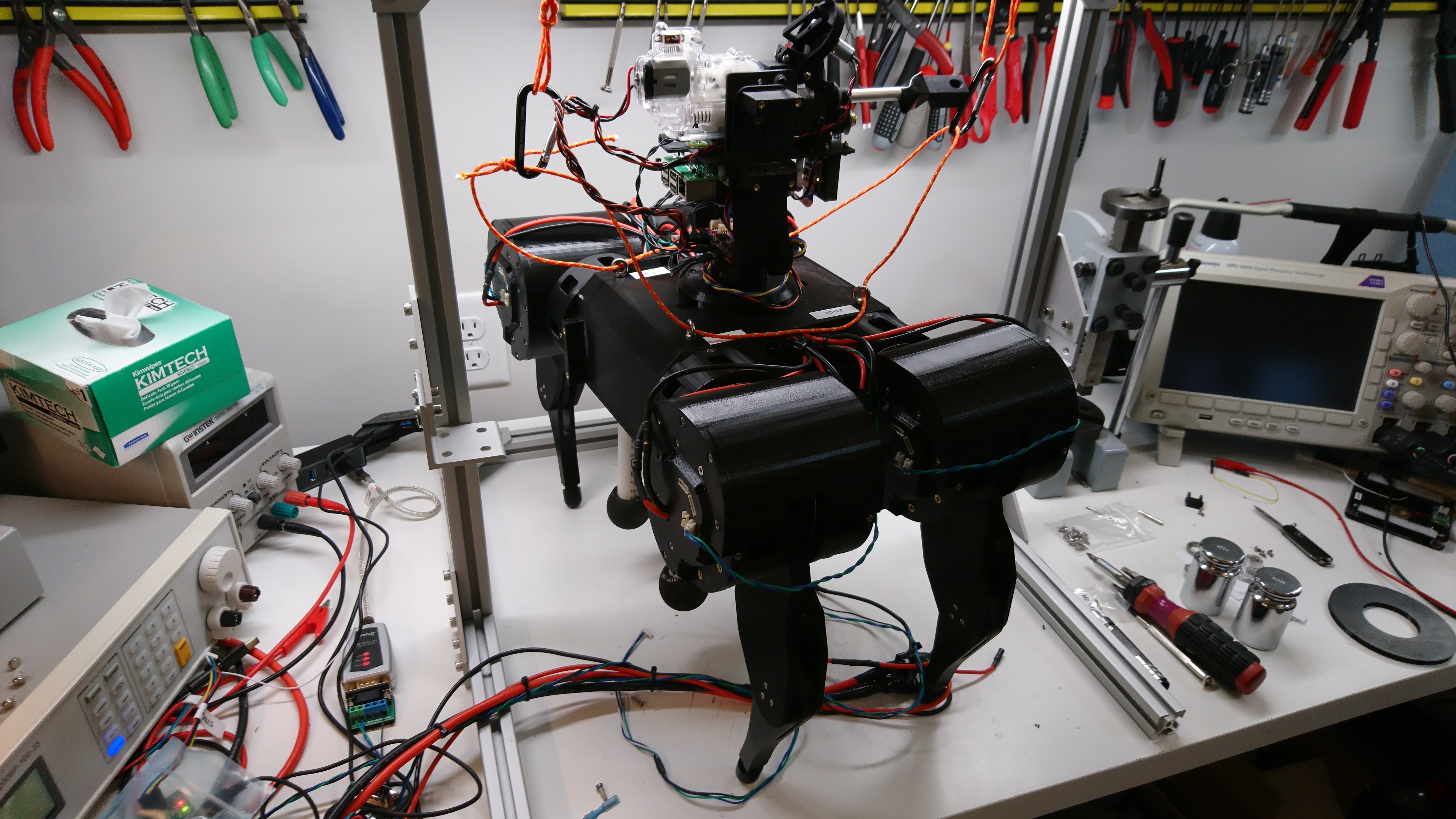
And, the entire first leg:
Done?
After carefully managing my 3d printing queue 24/7 to get all the legs, shoulders, and gearboxes printed, here’s a picture of all the legs on at the same time!
Next up… will it move?