Archives: Torque

Improved dynamometer

Long ago, in a workshop not so far away, I built a dynamometer for characterizing moteus controllers and motors. In the intervening 5 years, we released the moteus-r4.11, moteus-n1, moteus-c1, and now the moteus-x1! For each of these controllers, and the many firmware releases in between, this fixture has still served as a critical part of the validation procedure for new firmware releases and new product releases. However, it was time for a few improvements when tackling the moteus-x1, so here is a brief write up of the new result.

Measuring torque ripple

Recently I described some changes I made to improve the low speed torque ripple of the moteus controlle. I also built a dynamometer. I decided to use the dynamometer to quantify how much things had improved with the torque ripple, and to see how much room for improvement was left with any anti-cogging implementation.

Dynamometer script

Here, the test script is relatively simple. I have the “fixture” controller sweep at a very low velocity (0.01Hz) through a bit more than one full revolution using a relatively high I term in the PID controller to ensure that it really holds that position no matter what external torque is applied. Then, the “device under test” controller is just commanded either to be powered off, or in position mode with a pd gain of 0 and a feedforward torque. Then I can just measure the result from the torque transducer while this sweeps through a full revolution, and correlate the measured torque with the encoder position.

STM32G4 ADC and low-torque operation

Recently dlickindorf pointed out in the mjbots discord that he was having problems with very low torques on his large PMSM hobby-grade motor. While moteus doesn’t have any anti-cogging support yet, it should still be capable of driving motors such that the unexpected torque isn’t much worse than the baseline cogging torque of the motor. However, he was seeing much worse behavior with controlling to 0 current, as much as a full percent of the maximum torque of the motor.

Initial dynamometer assembly

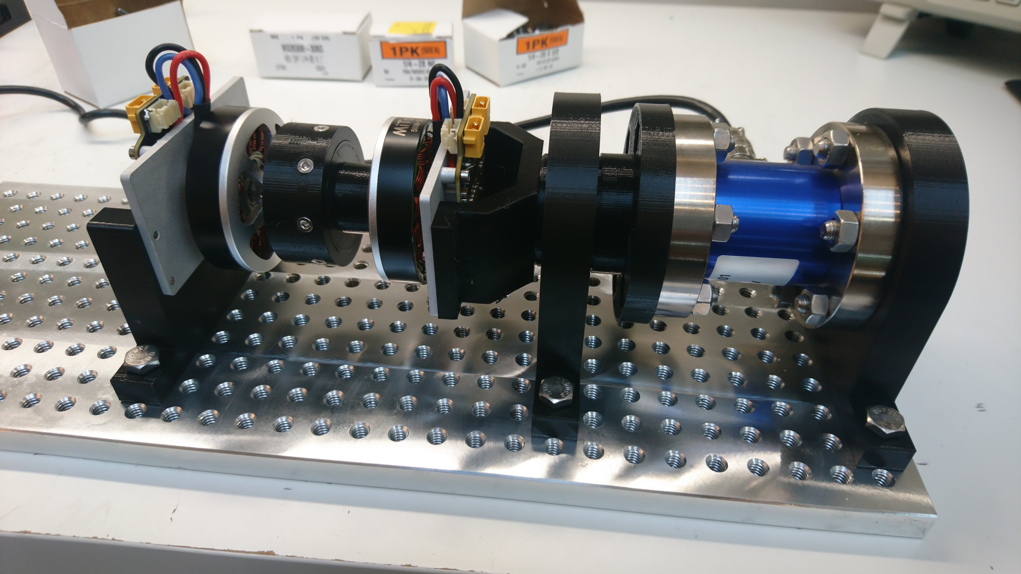
Earlier I showed off a torque transducer and the calibration fixture I used for it. I’ve now got enough assembled to make an entire dynamometer:

This has the torque transducer on one end, coupled to the “fixture” moteus controller through a bearing support. Then that is connected via a 3d printed coupler to the “device under test” moteus controller, which is hard mounted to the base plate. Any net torque between the two controllers will be coupled back to the transducer resulting in a measured torque.

Torque transducer

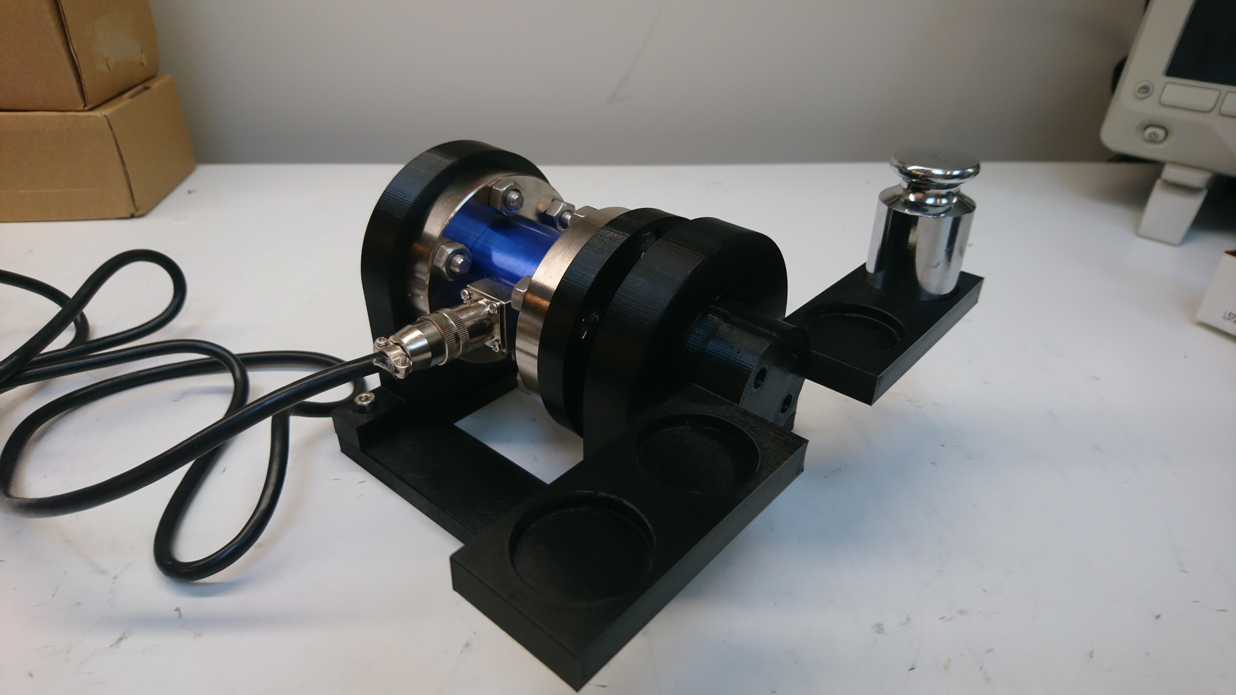
I’ve been wanting to build a dynamometer for a while to better characterize the performance of the direct drive and geared versions of the moteus controller. I have now started down that path with a torque transducer, which I calibrated with the below fixture:

I got a what ended up being a low quality load cell amplifier to use with it from the same supplier, although discovered it was total garbage and am now using a SparkFun OpenScale board which seems to be working much better. Soon I’ll hopefully have something wired up that actually has a controller or two on it.

Up-rating the qdd100 beta thermal bounds

When I first posted the qdd100 beta on mjbots.com, I performed a simple “continuous torque” test where I measured the torque that could be applied indefinitely without thermal limiting in a lab environment. It has come to my attention that other servos rate their “continuous torque” for a much lower value of “continuous”, sometimes only 30s. To make the situation clearer, I measured the time to thermal limiting at a range of torques and updated the product page.

Dealing with stator magnetic saturation

In my previous experiments demonstrating torque feedback (full rate inverse dynamics, ground truth torque testing), I’ve glossed over the fact that as the stator approaches magnetic saturation, the linear relationship between torque and current breaks down. Now finally I’ll take at least one step towards allowing moteus to accurately work in the torque domain as motors reach saturation.

Background

The stator in a rotor consists of windings wrapped around usually an iron core. The iron in the core consists of lots of little sub-domains of magnetized material, that normally are randomly oriented resulting in a net zero magnetic field. As current is applied to the windings, those domains line up, greatly magnifying the resulting magnetic field. Eventually most of the sub-domains are aligned, at which point you don’t get any more magnifying effect from the iron core. In this region, the stator is said to be “saturated”. You can read about it in much more depth on wikipedia or with even more detail here. The end result is a curve of magnetic field versus applied current that looks something like this:

Testing qdd100 stator windings

My initial design torque for the qdd100 was a little over 17 Nm. However, when I did my first ground truth torque testing, I found that some servos had a lower maximum torque than I had specified. While working to diagnose those, I built a qdd100 that used an alternate stator winding of 105Kv instead of the 135Kv that are in all the beta units. The Kv rating of a stator describes how fast the motor will spin for a given applied voltage. If you assume the same amount of copper mass of wiring, a lower Kv will mean that there are thinner wires that wrap around the stator more turns (or fewer wires in parallel). A higher Kv will have thicker wires with fewer overall turns.

Ground truth torque testing for qdd100

First, a limited number of qdd100 servos are available for sale to beta testers!  Check them out at mjbots.com.

After building up the first set of qdd100 servos, I wanted to empirically measure their performance parameters.  Some astute commenters uncovered in my terrible juggling video, that I didn’t actually have any ground truth measure of torque with these actuators.  Given that the ultimate torque is a pretty useful performance metric, it’s a good thing to have a solid understanding of.