Archives: Spi

Low cost off axis encoders for moteus - a beginning

The moteus line of brushless controllers all have an integrated “on-axis” magnetic encoder. These encoders are designed to allow moteus to sense the position of a motor’s shaft directly, assuming that an appropriate diametrically magnetized sense magnet is attached to the rotating shaft and the moteus is mounted so that its sensor is positioned over the magnet.

This works great for many applications, but what about hollow shaft motors? moteus supports a few encoder types that will work for off axis encoders, most notably is the AksIM-2. This is a high performance off-axis encoder that gives great performance and is manufactured in configurations for a variety of hollow shaft diameters. However, it does have downsides. First, it comes with a commensurate price tag. In single quantities, the AksIM-2 and magnetic code disc are more expensive than an entire moteus brushless motor controller. Second, only the moteus-n1 has the necessary RS422 transceiver integrated into it. All other moteus boards need an external RS422 transceiver.

Flexible I/O: Auxiliary port configuration

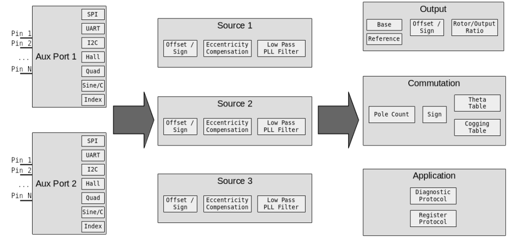
In the last post, I covered the goals behind more flexible I/O support in the moteus brushless controller. This time, I’ll start to cover the configuration model that I implemented to make that support work. It is broken up into 3 distinct phases, auxiliary ports, sources, and sinks.

Slightly simplified I/O structure flow diagram

Slightly simplified I/O structure flow diagram

Auxiliary port pin configuration

To begin with, the available connectors and external pins on moteus are organized into “auxiliary ports”. For the moteus r4.3/4.5/4.8/4.11, the correspondence is that the external primary encoder connector, if present (r4.8 and newer), is “auxiliary port 1”. The ABS port and some on-board debug pads are “auxiliary port 2”. For each port, there are two levels of configuration, at the pin level and the function level.

external primary encoders for moteus

With the r4.8 release of moteus, a not-yet-announced feature was included – the ability to have an off-board primary encoder! It didn’t get announced at the time, because the connectors necessary to populate the board were not obtainable. In fact, that is still the case, but I’ve located a substitute part which works well enough, so here we go!

Theory

The moteus controller uses an absolute magnetic encoder to determine the relationship between the rotor and stator of the motor at each given instant. That allows it to produce torque in the motor at any speed, from standstill to the maximum possible speed. Until now, the only magnetic encoder that was supported is the one mounted to the backside of the board. This is largely acceptable, as moteus is intended to be used in integrated applications.

Bringing up CAN on the quad pi3 hat

After getting the power to work, the next step in bringing up the new quad’s raspberry pi interface board is getting the FDCAN ports to work.  As described in my last roadmap, this board has multiple independent FDCAN buses.  There are 2 STM32G4’s each with 2 FDCAN buses so that every leg gets a separate bus.  There is a 5th auxiliary bus for any other peripherals driven from a third STM32G4.  All 3 of the STM32G4’s communicate with the raspberry pi as SPI slaves.

Bringing up the IMU on the pi3 hat

The next peripheral to get working on the quad’s raspberry pi interface board is the IMU. When operating, the IMU will primarily be used to determine attitude and angular pitch and roll rates.  Secondarily, it will determine yaw rate, although there is no provision within the IMU to determine absolute yaw.

To accomplish this, the board has a BMI088 6 axis accelerometer and gyroscope attached via SPI to the auxiliary STM32G4 along with discrete connections for interrupts.  This chip has 16 bit resolution for both sensors, decent claimed noise characteristics, and supposedly the ability to better reject high frequency vibrations as seen in robotic applications.  I am currently running the gyroscope at 1kHz, and the accelerometer at 800Hz.  The IMU is driven off the gyroscope, with the accelerometer sampled whenever the gyroscope has new data available.