First soft-jaws for CNC machining
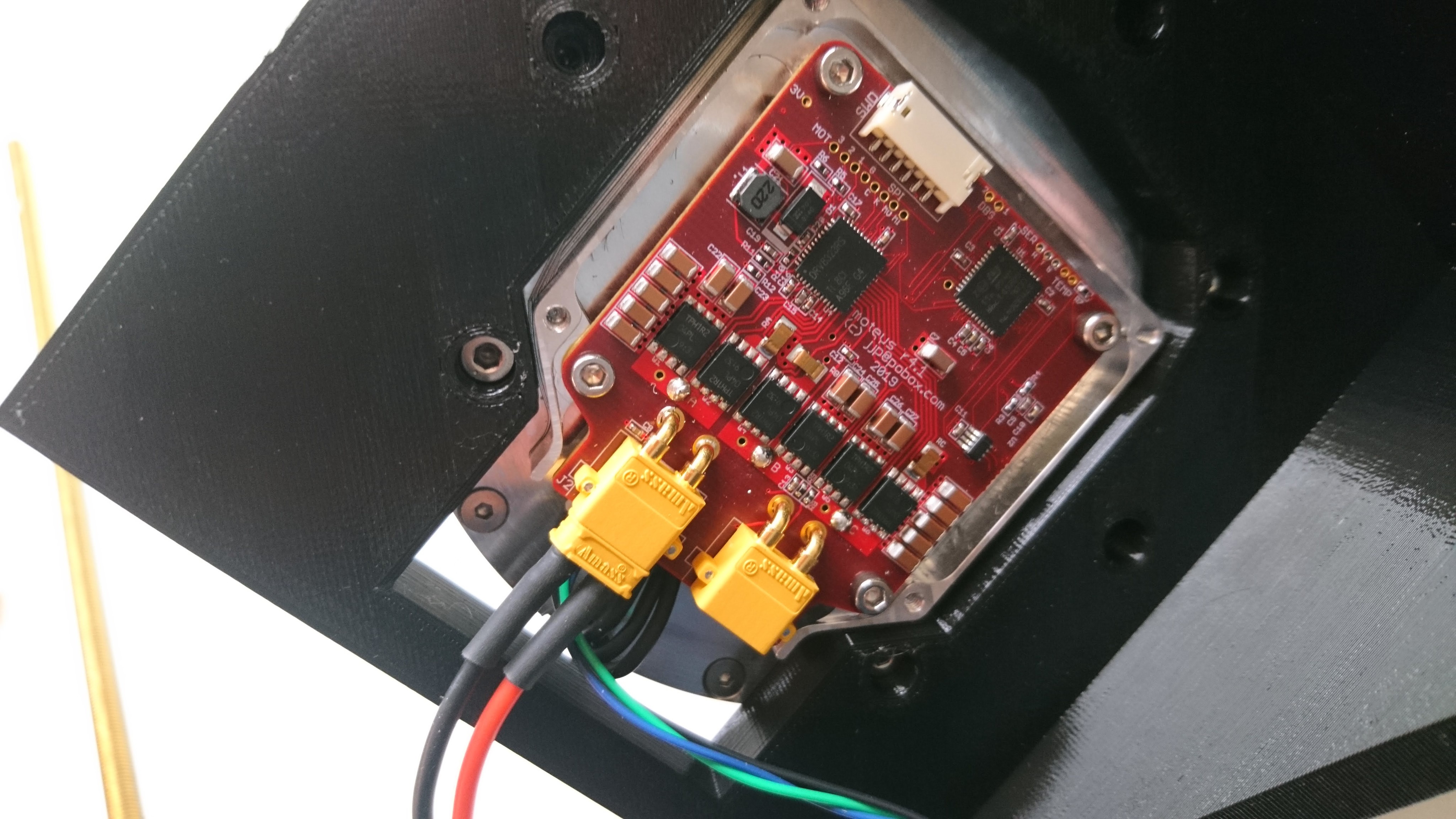
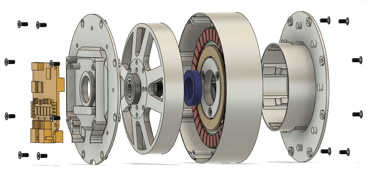
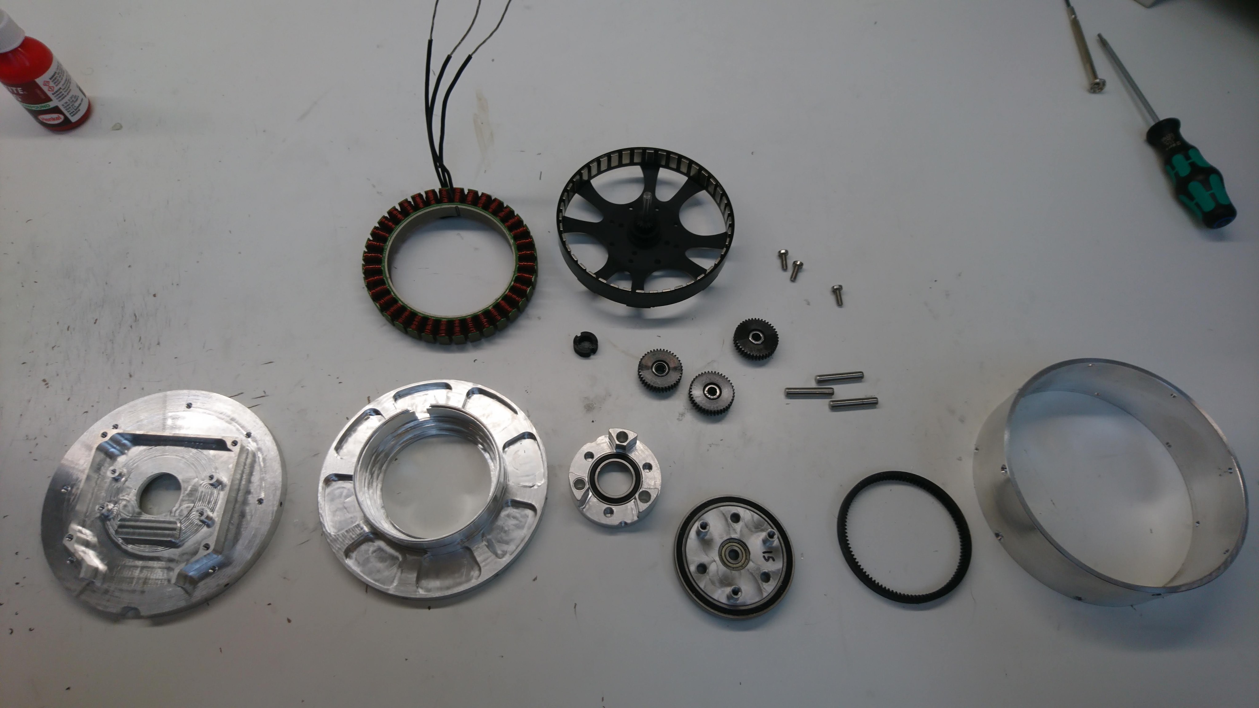
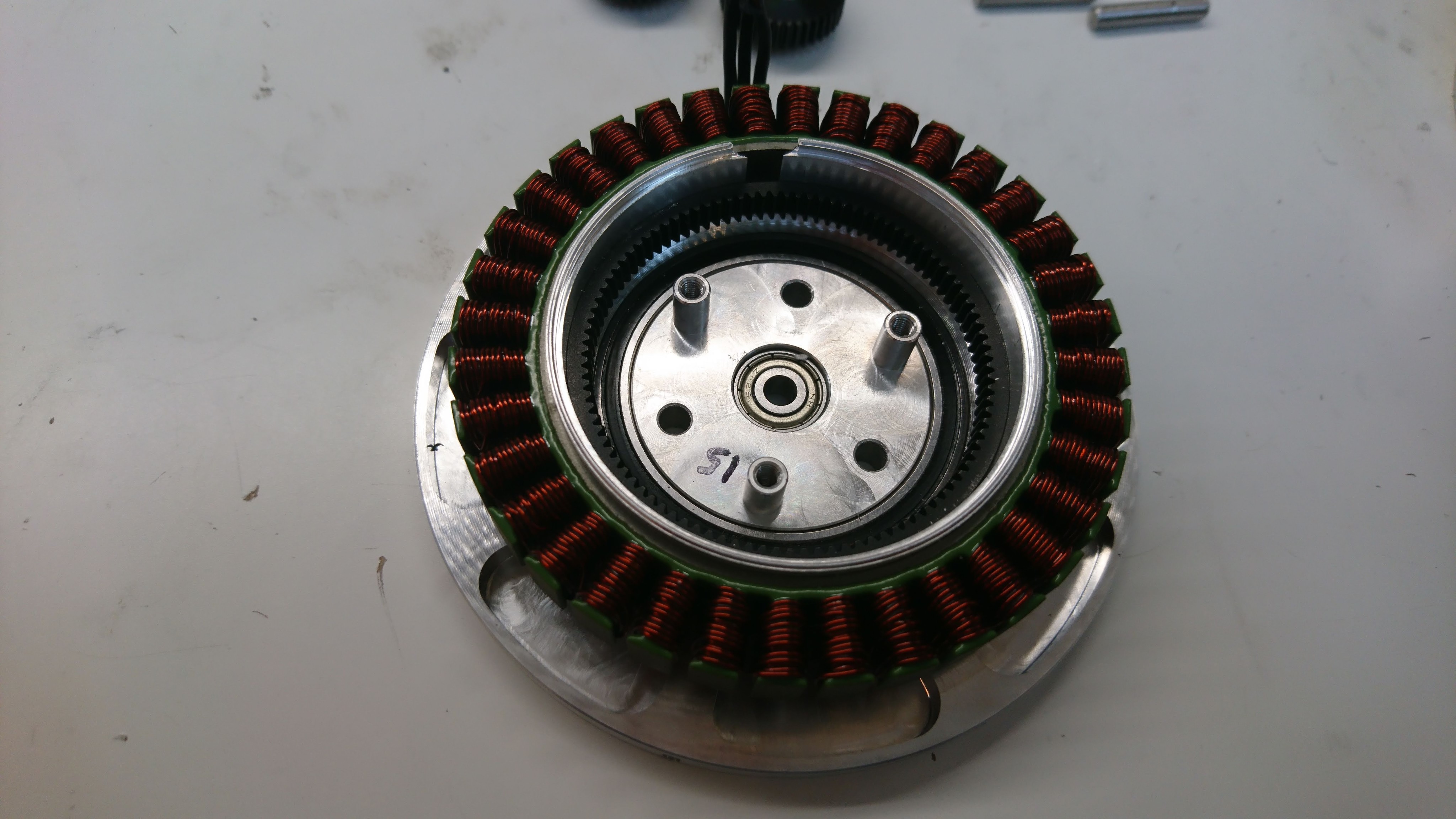
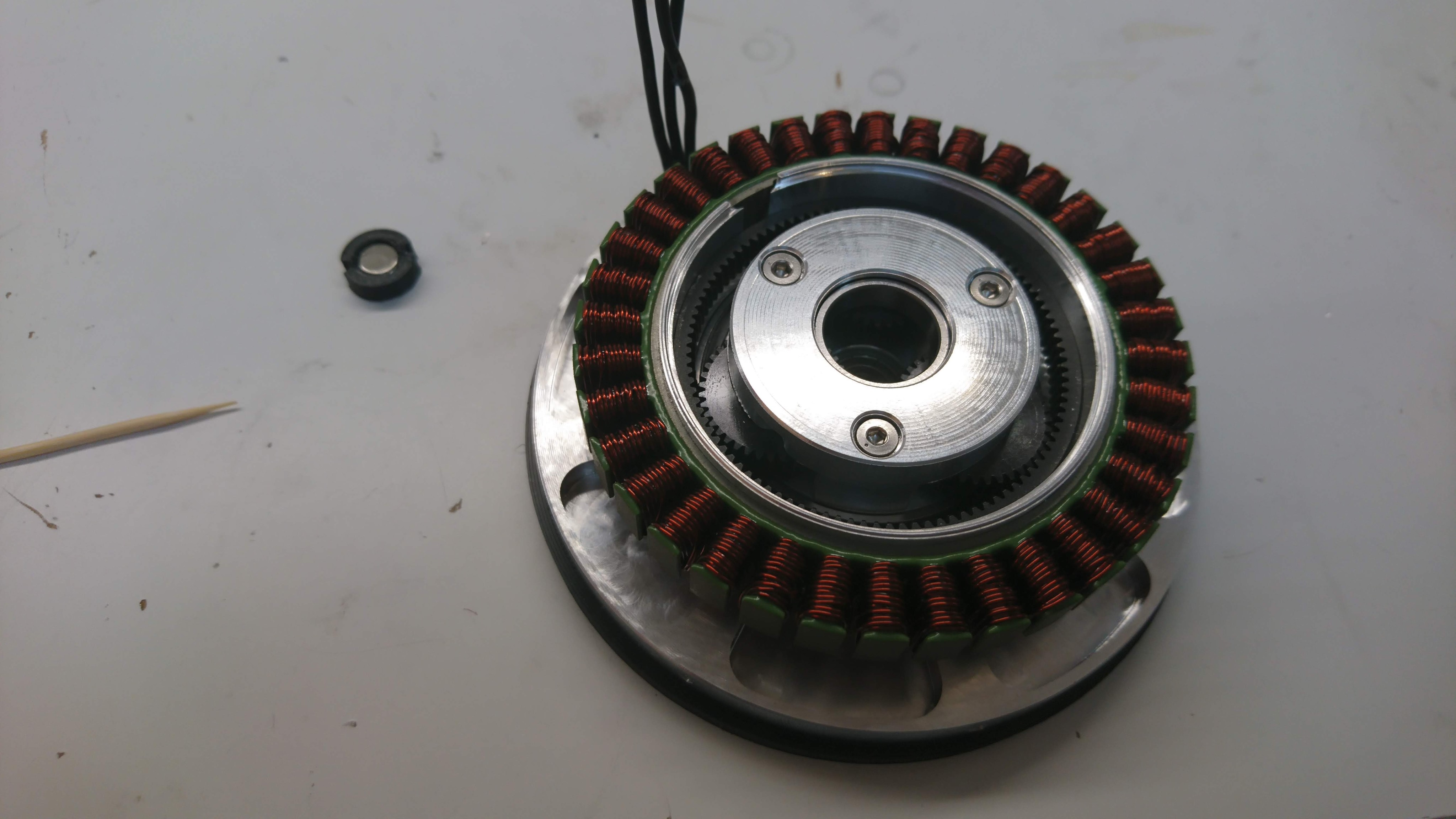
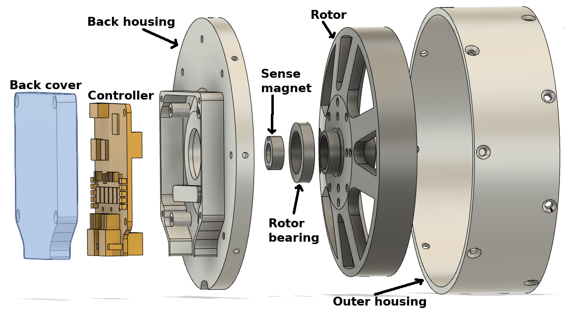
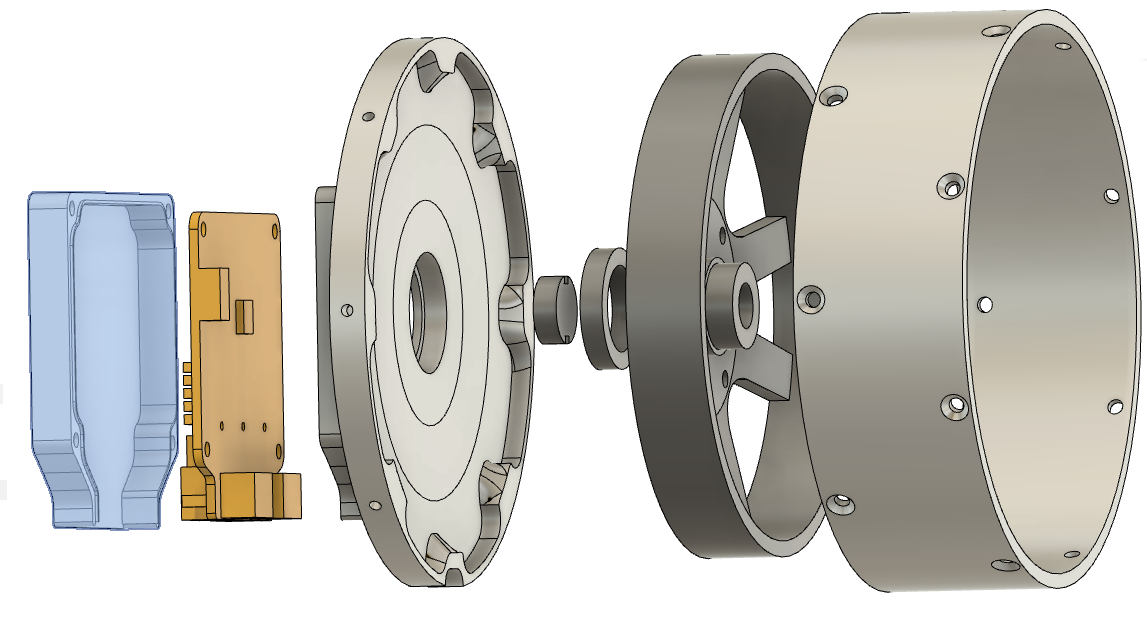
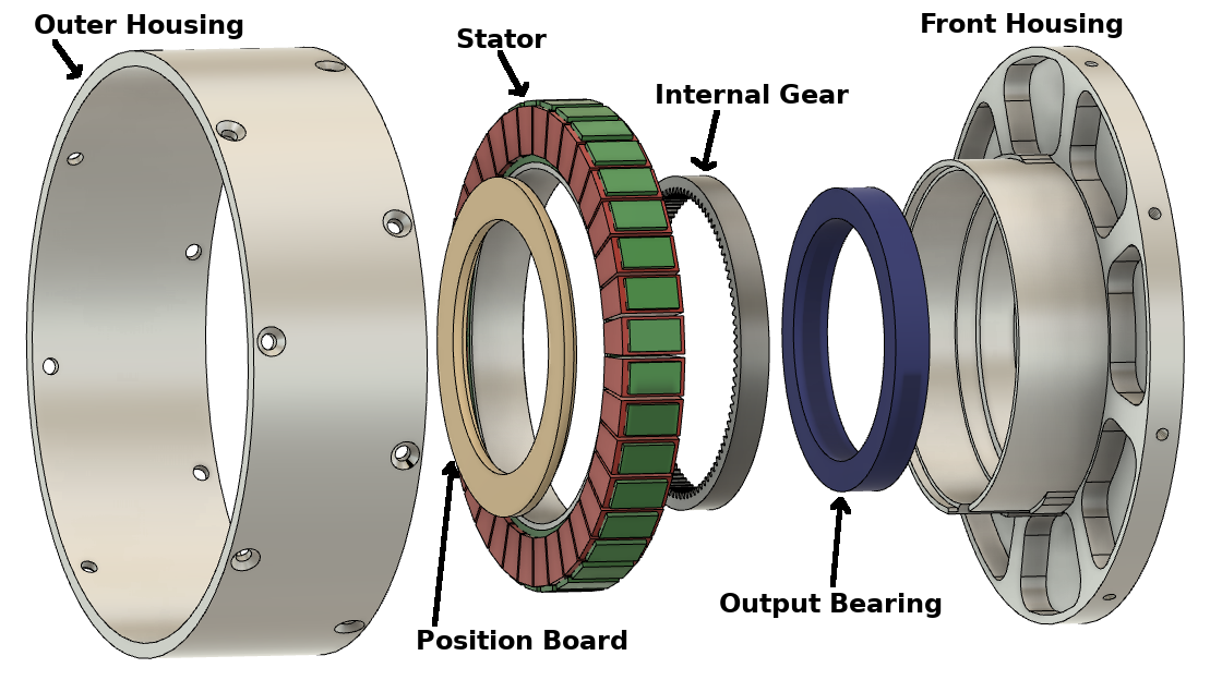
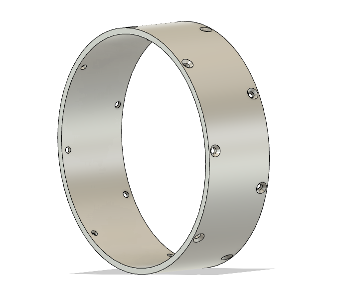
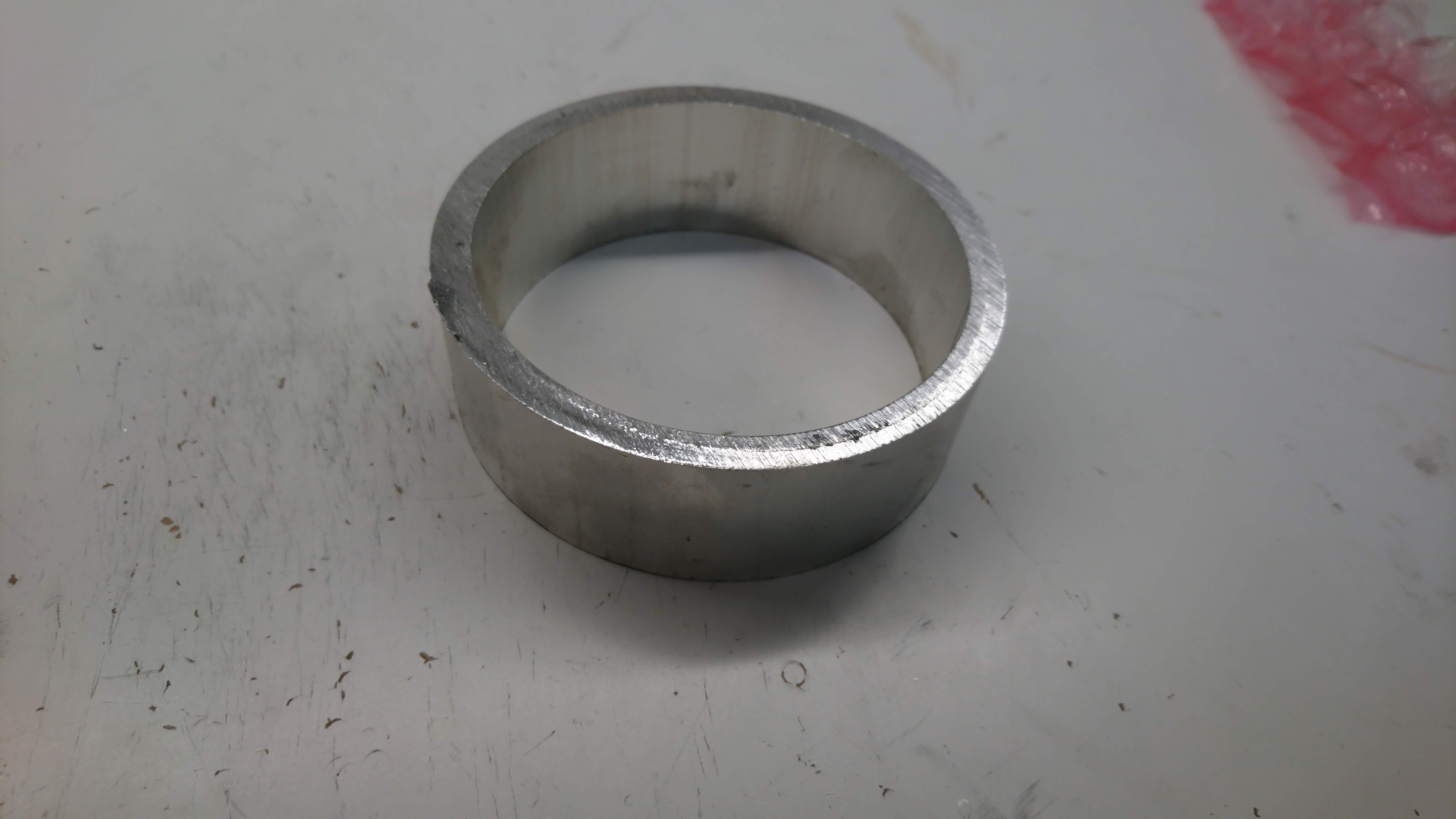
While working to build the reduced weight moteus servo mk2, I got tired of hand machining the first operation on a manual mill and lathe for the front and back housings. It was necessary, primarily to enable workholding on the PocketNC v2-50, but also because it allowed me to remove much of the excess material more quickly than could be done on the PNC. So, I got trained up on the AA CNC Bridgeport and went to town.