Archives: Rpi

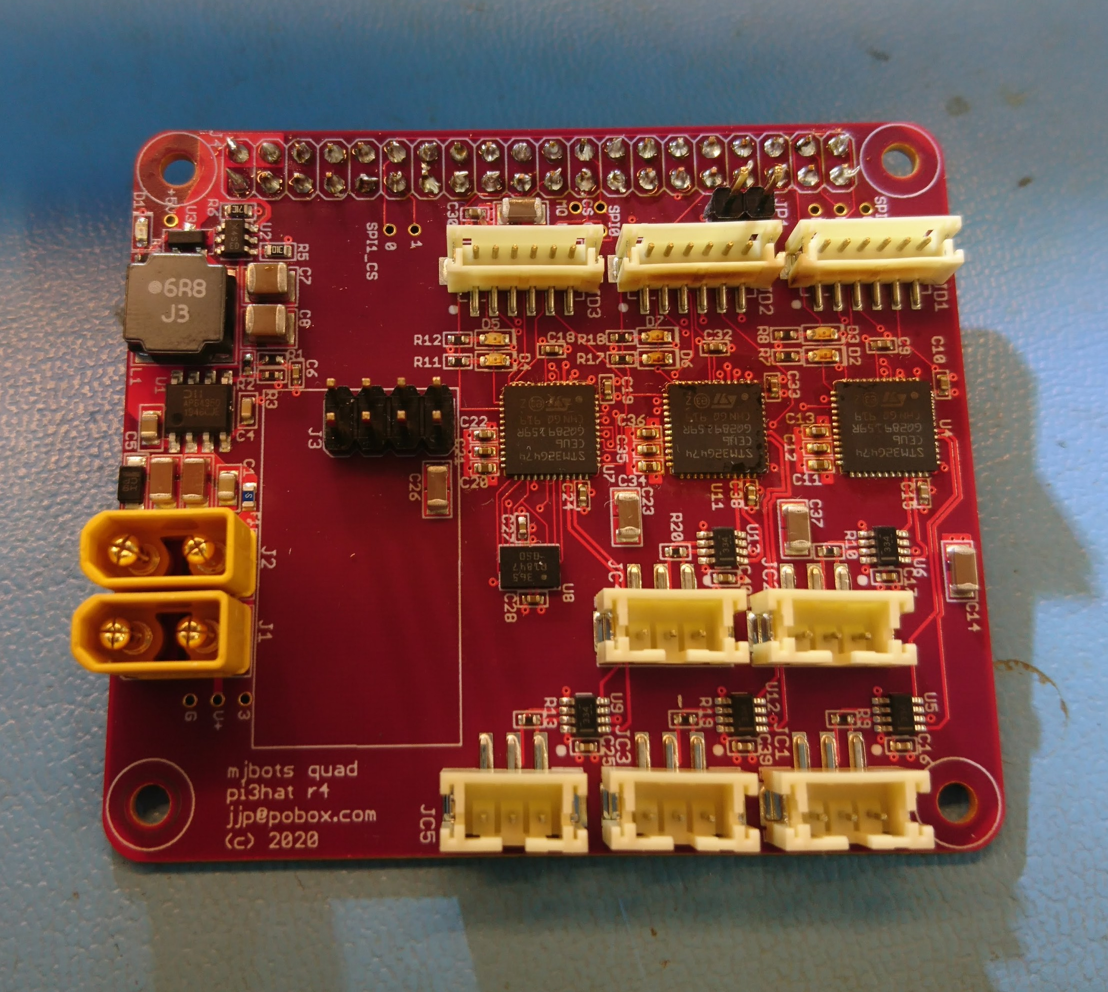
Bringing up the IMU on the pi3 hat

The next peripheral to get working on the quad’s raspberry pi interface board is the IMU. When operating, the IMU will primarily be used to determine attitude and angular pitch and roll rates.  Secondarily, it will determine yaw rate, although there is no provision within the IMU to determine absolute yaw.

To accomplish this, the board has a BMI088 6 axis accelerometer and gyroscope attached via SPI to the auxiliary STM32G4 along with discrete connections for interrupts.  This chip has 16 bit resolution for both sensors, decent claimed noise characteristics, and supposedly the ability to better reject high frequency vibrations as seen in robotic applications.  I am currently running the gyroscope at 1kHz, and the accelerometer at 800Hz.  The IMU is driven off the gyroscope, with the accelerometer sampled whenever the gyroscope has new data available.

Bringing up power on the quad pi3 hat

The first thing I needed to get working on the new quad’s raspberry pi3 hat, was the input DC/DC power converter.  One of the main functions of this board is to take the main DC bus voltage of around 20V, and provide the raspberry pi with 5V power.

In the previous iteration of this board, it was limited to an recommended maximum voltage of around 24V.  As with all the components in my hardware revisions I aimed to support a higher input voltage.  Here I switched parts to the Diodes AP64351 so that I could get to a recommended maximum voltage of 32V (the part’s absolute max is 40V).

New quad raspberry pi interface board

With the new FD-CAN based moteus controllers I need a way for the raspberry pi to communicate with them.  Thus I’ve got a new adapter board in house that I’m bringing up:

dsc_0339

This one has 5 independent FD-CAN channels, an IMU, a port for an nrf2401l RF transceiver as well as a buck converter to power the computer from the main battery bus.

The prototypes were largely constructed by MacroFab, although I did the Amass connectors and the STM32s because supply chain issues prevented me from getting those parts to MacroFab in time.

mjbots quad A0: October 2019 Roadmap

My last video gave an overview of what I’ve accomplished over the past year.  Now, let me talk about what I’m planning to work on going forward:

I intend to divide my efforts into two parallel tracks.  The first is to demonstrate increased capabilities and continue learning with the existing quad A0, and second is to design and manufacture the next revision of all its major components.

New capabilities and learning

The first, and most important capability I want to develop is an improved gait and locomotion system.  While the moteus servos in the quad A0 are capable of high rate compliant control, the gait engine that I’m using now is still basically the same one that I made for the HerkuleX servos 5 years ago.  It just commands open loop positions to each of the servos and uses no feedback from the platform at all.  This severely limits what the robot can do.  For instance, if the terrain is not level, legs will drag on the ground or it will not walk at all.  The maximum speed is relatively slow and achieving it requires careful tuning of servo-level gains.  While it is more robust than nearly any other open loop 4 legged walker while standing up, even small disturbances can cause it to fall over.

Improving the moteus update rate, part 4

In part 1, part 2, and part 3, I looked at what was limiting the update rate of the moteus controller when built into a quadruped configuration and how to improve that.  Now, it is time for the final demonstration!

That video was shot with a 150Hz overall update rate.  The plot shows the commanded and actual position of the three joints in the front right leg, although not all to the same vertical scale.  Updating the servos themselves only used about 3.5ms per cycle, but the gait logic used another 1-1.5ms, which made hitting 200Hz not super reliable, thus running at 150Hz.

Improving the moteus update rate, part 3

Back in part 1 and part 2, I looked at problems that limited the rate at which the host computer could command the full quadruped and some of the solutions.  Now, in part 3, I’ll cover more of the solution.

More solution steps

Previously, I switched to using PREEMPT_RT, switched bridging strategies, and optimized the turnaround of the individual servo.  Now, I’ll move on to optimizing the host software.

4. Host C++ software micro-optimizations

The primary contributor in the host software to the overall update rate is the time it takes to turn around from receiving a reply from one servo, to sending the next command.  I first did some easy micro-optimizations which came up in profiling.

Improving the moteus update rate, part 2

Back in part 1, I looked at the driving factors that limited the update rate of the full quadruped.  Now in part 2, I’ll cover the first half of the solution.

Background

To begin with, there were two major paths that I could take based around the network topology.  In one path, I would remove the active bridging capability from the junction board, and rely on the Raspberry Pi to drive all the servos directly, and in the other the active bridge would stick around.  There were a number of key disadvantages to both approaches:

Improving the moteus update rate, part 1

The moteus brushless controller I’ve developed for the force controlled quadruped uses an RS485 based command-response communication protocol.  To complete a full control cycle, the controlling computer needs to send new commands to each servo and read the current state back from each of them.  While I designed the system to be capable of high rate all-system updates, my initial implementation took a lot of shortcuts.  The result being that for all my testing so far, the outgoing update rate has been 100Hz, but state read back from the servos has been more at like 10Hz.  Here I’ll cover my work to get that rate both symmetric, and higher.

Pocket NC Raspberry Pi Wifi Bridge

The primary UI the Pocket NC presents is a web interface accessible over a virtual USB based ethernet port.  I wanted to be able to run mine not immediately near an ethernet jack, but also didn’t want to have to tote a laptop over every time to check on it.  I had plenty of raspberry pi’s lying around, so rigged one up as a wifi bridge.

First, I found a random case to print from thingiverse, the TurboPi:

rpi3 interface board

Now that I have a chassis that can walk a little bit, I need to get the onboard computer working.  To do that, I needed to update the raspberry pi 3 daughterboard I built for the previous turret for the new bus voltage and communication format.

The rpi3’s UART is incapable of controlling the direction line on the RS485 transceiver, so I added a small STM32 micro in line to control the transmit / receive direction.  It adds a little bit of latency, but testing the firmware I was able to get it down to only a byte’s worth or so.