Archives: Rpi

5 Side PCB Test Fixture

If you look around online, there are lots of examples of PCB test fixtures used to perform end of line testing. In the low to medium volume scale, nearly all of these are either clamshell or 2 side affairs, where probe pogo pins or interfaces are connected to the bottom and top of the board.

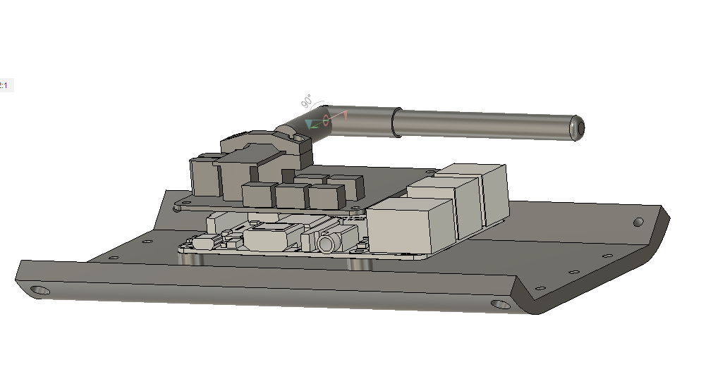
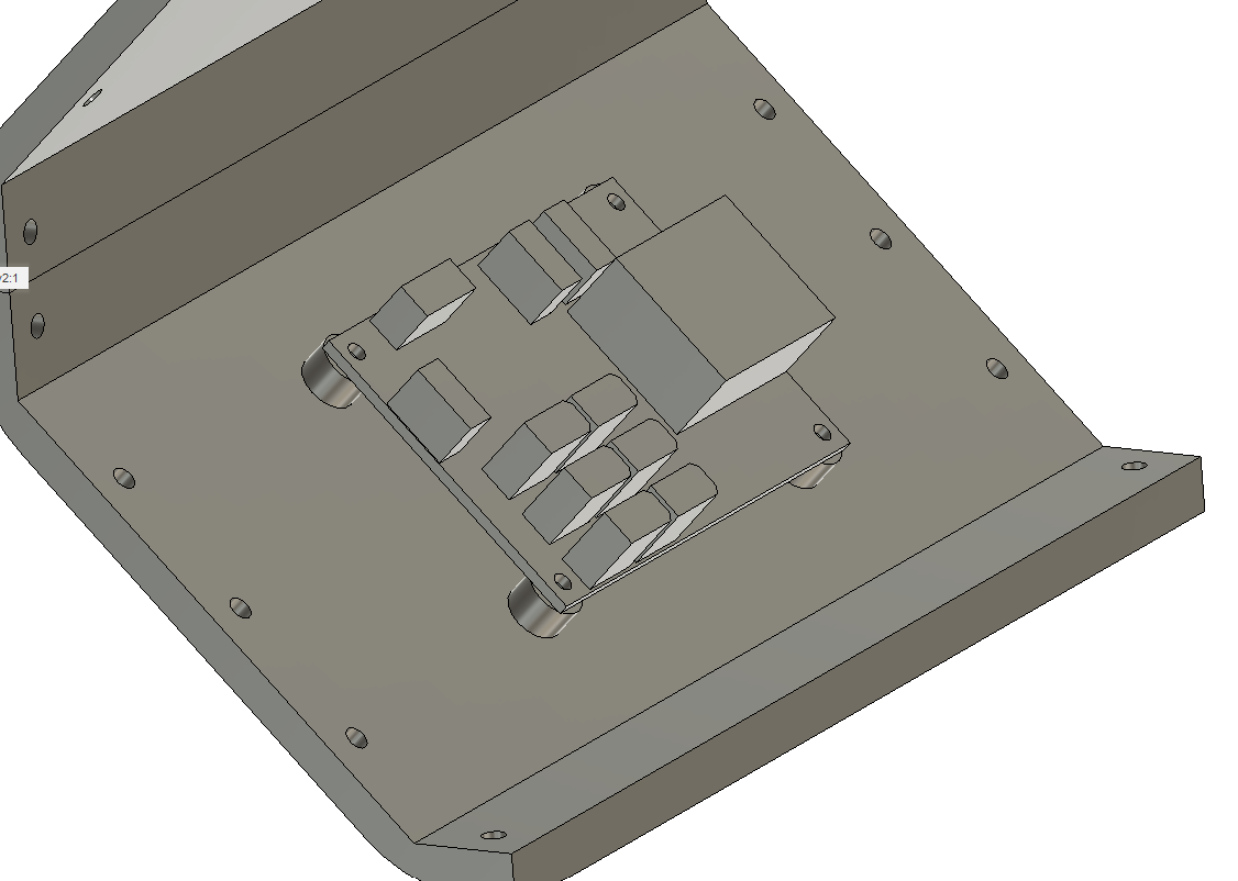
When developing the moteus-n1, one of the challenges was the number of right angle board edge connectors it has. Those right angle connectors are what allow it to maintain a very low overall stack height when installed in applications, but are also much harder to perform testing on, since by definition the access points are not vertical. On the base n1, there are 6 total right angle connectors, 2 on each of 3 sides, and future variants may have additional bottom side CAN and power connectors populated to make 8 total right angle connectors.

Updated moteus test fixture

I documented the first test fixture I built for moteus some time ago. As the shipment volumes have gone up, the fixture became something of a limitation, and also was a little problematic in a few ways.

The old “state of the art”

First, it relied on attaching 3 connectors by hand for each test, which was a decent fraction of the cycle time. Second, the pogo pins it used were non-replaceable, and also connected only to the debug phase wire test vias, which were tiny. They wore out relatively quickly, and replacing them required building a whole new board. Finally, since the pogo pins were PCB mounted, a PCB needed to be printed for any change in the pin locations or which pins to probe.

New cross-platform moteus tools!

After receiving many requests via youtube, discord, and email, I’ve finally gone ahead, bitten the bullet, and updated all of the moteus tools to be pure python and work in a cross platform manner. Now, the only thing you need to do to install pre-compiled versions of tview and moteus tool on most* platforms is:

pip3 install moteus_gui
python3 -m moteus_gui.tview    # (or maybe just tview)
python3 -m moteus.moteus_tool  # (or maybe just moteus_tool)

I’ve personally tested these on Linux, Windows, and Raspberry Pi, and others have at least verified basic operation on Macs. Python 3.7 or greater is required.

Measuring the pi3hat r4.2 performance

Last time I covered the new software library that I wrote to help use all the features of the pi3hat, in an efficient manner. This time, I’ll cover how I measured the performance of the result, and talk about how it can be integrated into a robotic control system.

pi3hat r4.2 available at mjbots.com

pi3hat r4.2 available at mjbots.com

Test Setup

To check out the timing, I wired up a pi3hat into the quad A1 and used the oscilloscope to probe one of the SPI clocks and CAN bus 1 and 3.

Bringing up the pi3hat r4.2

The pi3hat r4.2, now in the mjbots store, has only minor hardware changes from the r4 and r4.1 versions. What has changed in a bigger way is the firmware, and the software that is available to interface with it. The interface software for the previous versions was tightly coupled to the quad A1s overall codebase, that made it basically impossible to use with without significant rework. So, that rework is what I’ve done with the new libpi3hat library:

New product Monday: pi3hat

I’ve now got the last custom board from the quad A1 up in the mjbots store for sale, the mjbots pi3 hat for $129.

This board breaks out 4x 5Mbps CAN-FD ports, 1 low speed CAN port, a 1kHz IMU and a port for a nrf24l01. Despite its name, it works just fine with the Rasbperry Pi 4 in addition to the 3b+ I have tested with mostly to date. I also have a new user-space library for interfacing with it that I will document in some upcoming posts. That library makes it pretty easy to use in a variety of applications.

Raspberry Pi 4

Only 1 full year after it was released, I managed to get a Raspberry Pi 4 and test it out in the quad A1. I had been delaying doing so because of reports of thermal issues. The Pi 3B+ already ran a little hot and I didn’t want to have to add active cooling into the robot chassis to get it stable.

It looks like the Raspberry Pi engineers have been hard at work because the newer firmware releases have significantly reduced the overall power consumption and thus the thermal load. In my testing so far it only seems “a little” hotter than the 3b+.

Primitive turret automatic tracking

Continuing in my series of developments with the Mech Warfare turret, I’ve now managed to replicate the primitive target tracking functionality I had in the v2 version of the turret.  This works using a pretty simple principle:

  • raspicam is used to read the raspberry pi camera
  • ArUco is used to find any fiducials in view
  • The target closest to the center is deemed, the “active target”
  • The pitch and yaw rate are set based on a simple P controller to bring that target to a known point

This works passably, as shown in the video below:

quad A1 chassis updates

I finally got around to fixing a number of minor glitches in the quad A1’s chassis recently.

1. The raspberry pi is now far enough away from the left panel that you can connect the HDMI if you choose.

20200506-rpi_mounting

2. I no longer have vestigal studs for the pre quad A0 junction board on the other side.

20200506-power_dist

3. The switch got moved down to between the legs.

dsc_0631