Archives: Quada1

Leg zeroing fixture

As part of provisioning a quad A1, or anytime the mechanical configuration has been changed, I need to go and record where the zero position of all the joints is.  The “0” position for the software now is with the shoulders perfectly horizontal, and the upper and lower leg sticking straight down.

Up until now, every time I’ve done this it has just been by eyeballing and with lots of foam and bubble wrap to shim things into place long enough to record the level.  Sometimes I had to go back and try a few times, as even determining when something is straight is not, well, straightforward.

New Mech Warfare turret

Another of the tasks I’ve set for myself with regards to future Mech Warfare competitions is redesigning the turret.  The previous turret I built had some novel technical features, such as active inertial gimbal stabilization and automatic optical target tracking, however it had some problems too.  The biggest one for my purposes now, was that it still used the old RS485 based protocol and not the new CAN-FD based one.  Second, the turret had some dynamic stability and rigidity issues.  The magazine consisted of an aluminum tube sticking out of the top which made the entire thing very top heavy.  The 3d printed fork is the same I one I had made at Shapeways 5 years ago.  It is amazingly flexible in the lateral direction, which results in a lot of undesired oscillation if the base platform isn’t perfectly stable.  I’ve learned a lot about 3d printing and mechanical design in the meantime (but of course still have a seemingly infinite amount more to learn!) and think I can do better.  Finally, cable management between the top and bottom was always challenging.  You want to have a large range of motion, but keeping power and data flowing between the two rotating sections was never easy.

Updated quad pi3 hat

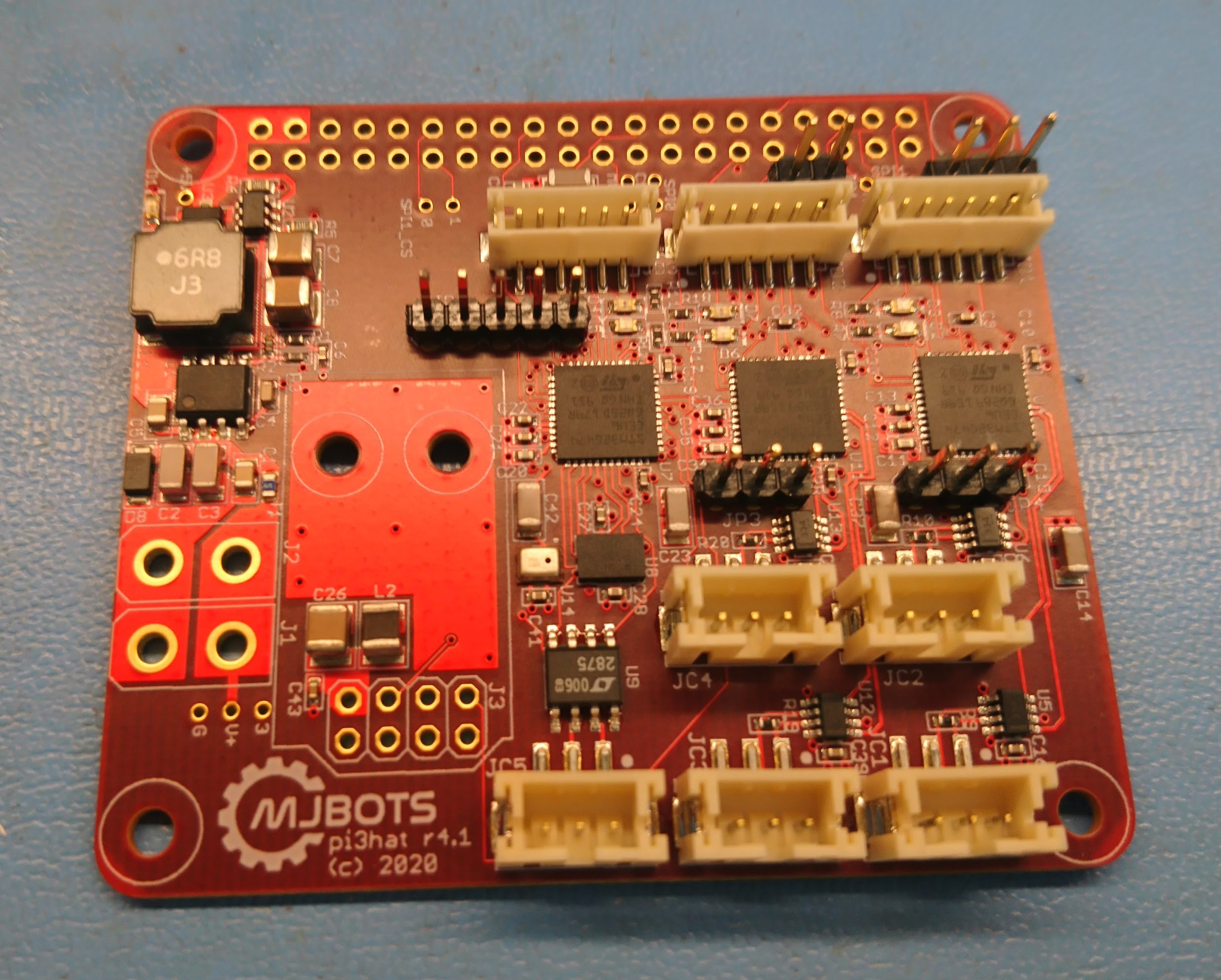
I made a number of tweaks to the quad A1’s raspberry pi hat to get it ready for production, resulting in r4.1 of the board:

dsc_0491

None of the changes were particularly big, but each has some value:

  • The correct switch mode regulator is installed.
  • The auxiliary CAN transceiver was switched to one that supports a larger common mode voltage.  This will allow it to be connected to the power distribution board without smoking.
  • Each of the STM32s now has some GPIO pins connected directly to GPIOs on the raspberry PI primarily to be used for interrupts.
  • Pin headers expose a few gpio pins from each STM32 for interfacing with random external things.
  • The NRF radio module changed orientation and has improved power filtering.
  • I added a microphone to the auxiliary STM32.  The goal is to eventually be able to use that to synchronize external video with onboard data collected during operation more easily.

I’ll bring this up in a future post!

quad A1 leg updates

When I first designed the full rotation leg, I didn’t fully appreciate the importance of torque in the knee joint.  Despite the fact that my first force based IK showed that when the legs are immediately under the body, the knee joint carries the entire load of the robot, I still managed to not add any reduction there.

The initial design used a 1:1 ratio, because that allowed me to use the same single piece 3d printed gear design I had used before.  A 28 tooth gear with 5mm pitch resulted in a gear that was larger than the output plate on the qdd100 servo, so it could just be bolted directly on.  To work with a smaller number of teeth, I had to split the gear into two parts, connected by pins, as the gear is now smaller than the qdd100 output plate.

Overlaying video on telemetry data with ffmpeg and OpenGL

While not its primary purpose, I still plan on entering my walking robots in Mech Warfare events when I can.  In that competition, pilots operate the robots remotely, using FPV video feeds.  I eventually aim to get my inertially stabilized turret working again, and when it is working I would like to be able to overlay the telemetry and targeting information on top of the video.

In our previous incarnation of Super Mega Microbot, we had a simple UI which accomplished that purpose, although it had some limitations.  Being based on gstreamer, it was difficult to integrate with other software.  Rendering things in a performant manner on top was certainly possible, although it was challenging enough that in the end we did nothing but render text as that didn’t require quite the extremes of hoop jumping.  Unfortunately, that meant things like the targeting reticule and other features were just ASCII art carefully positioned on the screen.

Spread spectrum integration

I’ve been developing a new bi-directional spread spectrum radio to command and control the mjbots quad robot.  Here I’ll describe my first integration of the protocol into the robot.

To complete that integration, I took the library I had designed for the nrfusb, and ported it to run on the auxiliary controller of the pi3 hat.  This controller also controls the IMU and an auxiliary CAN-FD bus.  It is connected to one of the SPI buses on the raspberry pi.  Here, it was just a matter of exposing an appropriate SPI protocol that would allow the raspberry pi to receive and transmit packets.

Resurrected quadruped simulator

Thankfully, I’m now at the point where I’m fixing actual dynamics problems on the robot.  Doubly thankfully I have a robot which is pretty robust and keeps working!  That said, it is still, shall we say, “non-ideal”, to be testing code for the first time ever on a real robot.

Back with my HerkuleX based Super Mega MicroBot, I had a working DART based simulation which was decently accurate.  However, the actuators for that machine were so limited that it didn’t really make sense to do any work in simulation.  The only way to be effective with that machine was to tweak and tweak on the real platform and rely on exactly the right amount of bouncing and wiggling that would get it moving smoothly.

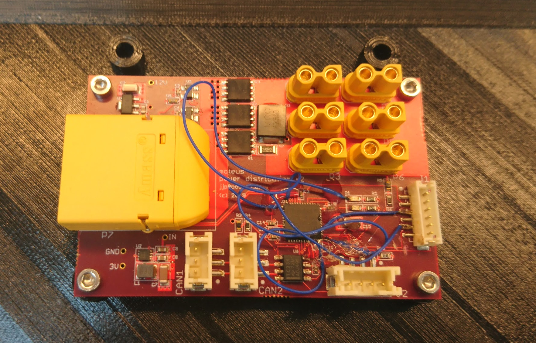
Power distribution board r3

While I was able to make the r2 power distribution board work, it did require quite a bit more than my usual number of blue wires and careful trace cutting.

dsc_0394

Thus I spun a new revision r3, basically just to fix all the blue wires so that I could have some spares without having to worry about the robustness of my hot glue.  While I was at it, I updated the logo:

nrfusb

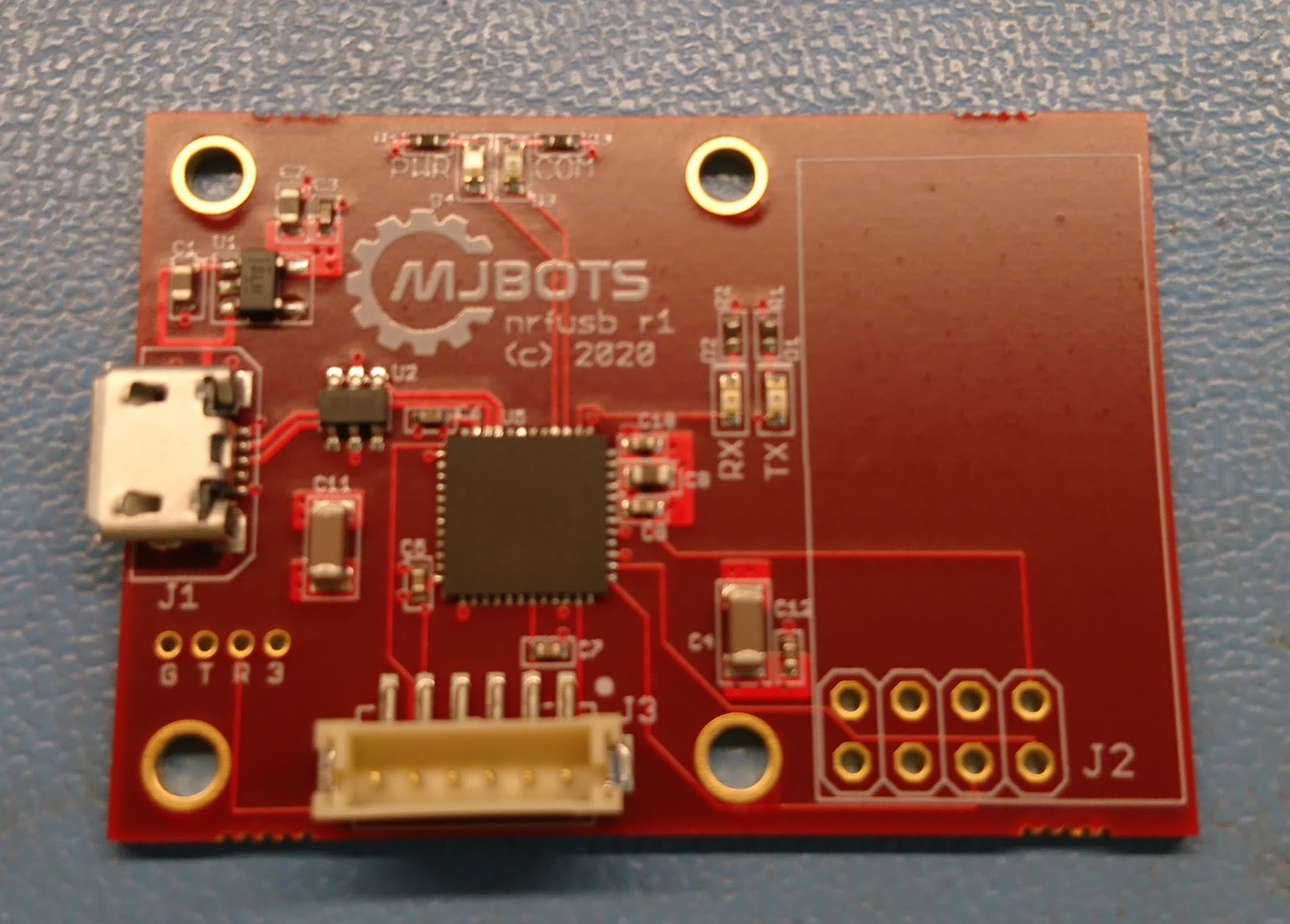
In order to bring up the final piece of the raspberry pi 3 hat, the nrf24l01+, I wanted a desktop development platform that would allow for system bringup and also be useful as a PC side transmitter.  Thus, the nrfusb:

dsc_0367

Similar to the fdcanusb, it is just an STM32G474 on the USB bus, although this has a pin header for a common nrf24l01+ form factor daughterboard.

The next steps here are to get this working at all, then implement a spread spectrum bidirectional protocol for control and telemetry.

Simple walking gait on the quad A1

After I restructured my control laws to take advantage of high rate force feedback for the pronking experiments, I haven’t actually managed to port the walking gait yet.  Now that I have a brand new robot, it seemed like a good time!

This gait is basically the same thing as I ran on the quad A0 in principle.  The opposing feet are picked up according to a rigid schedule, and moved to a point opposite their “idle” position based on the current movement speed.  Any feet that are completely placed on the ground just move with the inverse of the robot’s velocity.