Archives: Quada1

micro-BOM management

I’ve now built 3 or 4 complete quad A1 style robots depending upon how you look at it. Each was somewhat of a one-off, incrementally modified over time as I discovered failure modes and improved the design. Before starting to serially build quad A1 style robots, I wanted to get a better understanding of how much actually goes into making one. The quad A1 has a fair number of sub-assemblies, custom PCBs, harnesses, and assembly steps that go into its production. During previous builds, I kept running into problems where I would run out of some component, fastener, or raw material unexpectedly, then have to wait for its lead time before I could continue.

Testing real-life hill operation

In part 1, part 2, and part 3 of this series, I developed a method for keeping the robot balanced on hills in simulation. This is just a short video update demonstrating the results for a variety of gaits on a gentle-ish hill (the slope is around 7 degrees).

Balancing on estimated terrain

Last time, I described my approach for estimating the terrain under the robot based on the inertial measurement unit and proprioceptive foot feedback. Now, I’ll cover how that is used to balance.

“R” Frame

First, let me explain the “R” or “robot” frame and how it is used. The frames I’ve discussed in this series so far are the “B” frame, which is rigidly attached to the center of the robot body, the “M” frame, which is located at the center of mass and level with the ground, and the “T” frame, which is under the robot and level with the current terrain.

Estimating terrain slope

Last time I discussed the challenges when operating the mjbots quad A1 on sloped surfaces. While there are a number of possible means of tackling this, the approach I’ve gone with for now is to estimate the slope of the terrain under the robot, and use that to determine how to position the center of mass. Here’ll I’ll cover the estimation part of this solution.

On paper, the quad A1 has plenty of information to estimate the terrain under its feet. Between the IMU with attitude estimator, the proprioceptive feedback from the joints, and the ability to move the feet around, it would be obvious to a human whether the ground under them was sloped or level. The challenge here is to devise an algorithm to do so, despite the noise in the IMU, the fact that the feet are not always on the ground, and that as the robot moves, the terrain under it changes.

Operating on sloped surfaces

Not too long ago, I ran some outdoor experiments, and while piloting the quad A1 around, realized that it wasn’t going to get very far if it was restricted to just flat ground.

Since the control algorithms are completely ignorant of slopes, the center of gravity of the machine can easily get too close to the support polygon when resting, and similarly fails to stay balanced over the support line during the trot gait.

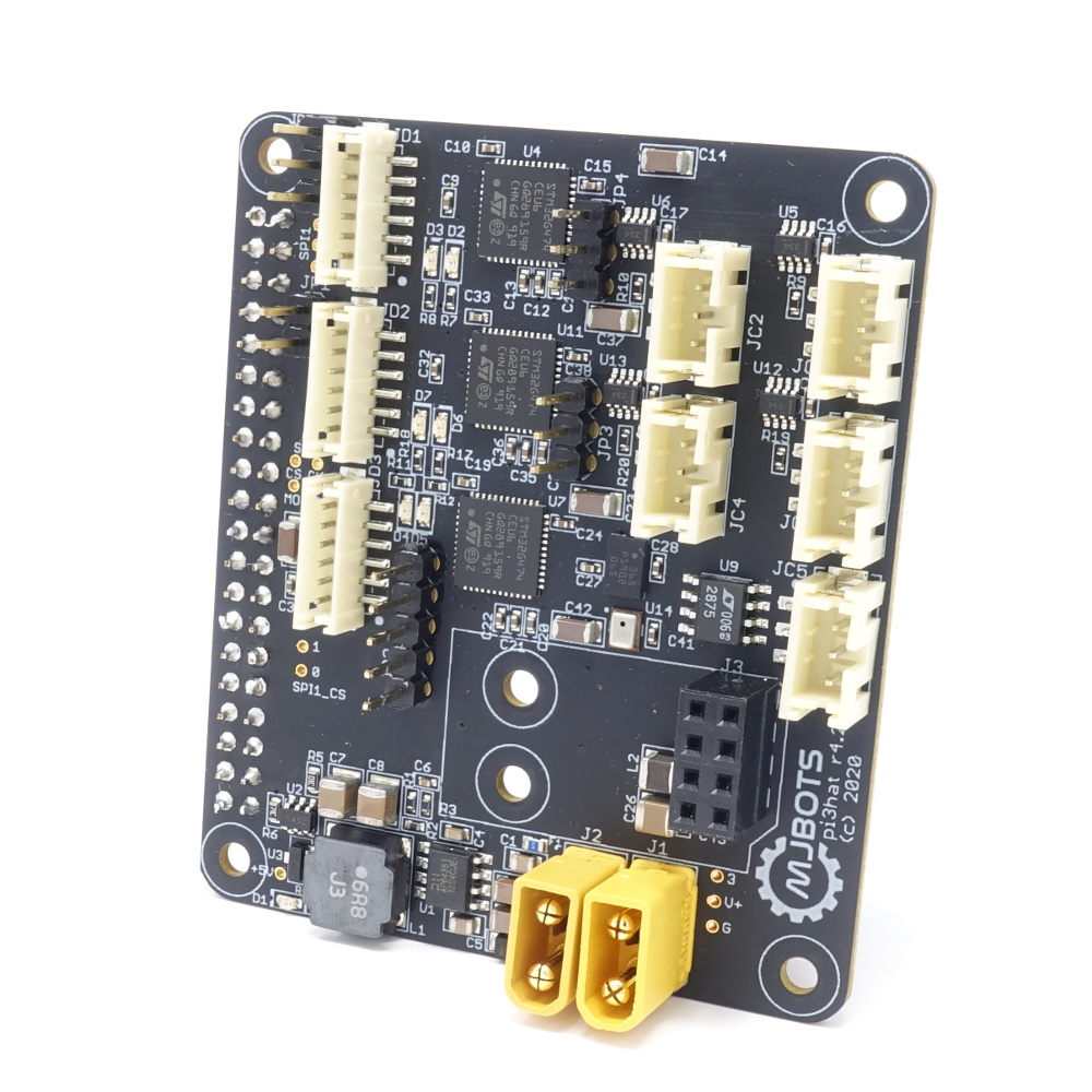
New product Monday: pi3hat

I’ve now got the last custom board from the quad A1 up in the mjbots store for sale, the mjbots pi3 hat for $129.

This board breaks out 4x 5Mbps CAN-FD ports, 1 low speed CAN port, a 1kHz IMU and a port for a nrf24l01. Despite its name, it works just fine with the Rasbperry Pi 4 in addition to the 3b+ I have tested with mostly to date. I also have a new user-space library for interfacing with it that I will document in some upcoming posts. That library makes it pretty easy to use in a variety of applications.

Raspberry Pi 4

Only 1 full year after it was released, I managed to get a Raspberry Pi 4 and test it out in the quad A1. I had been delaying doing so because of reports of thermal issues. The Pi 3B+ already ran a little hot and I didn’t want to have to add active cooling into the robot chassis to get it stable.

It looks like the Raspberry Pi engineers have been hard at work because the newer firmware releases have significantly reduced the overall power consumption and thus the thermal load. In my testing so far it only seems “a little” hotter than the 3b+.

Balancing gait in 2D

After getting a gait which looked like it could balance across the leg support line in 1D, I needed to extend that to 2D and try it out on the robot.

Extension to 2D

Extending this to two dimensions wasn’t too bad. I just did a bunch of geometry to follow the path traced out by a given 2 dimensional velocity and rotation rate, intersected with a line segment:

Given this function, the logic to select a swing target is basically the same as in the 1 dimensional case. We now create two “virtual legs”, which consist of two feet ganged together and produce a single support line. At each time instant when all legs are in stance, we look at the time remaining until each of the virtual legs would cross the center of mass at the current velocity. As soon as one hits the half-swing point, we start a swing.

Primitive gait balancing - 1D

I’m working to improve the walking gait of the mjbots quad A1. In this iteration, I wanted to tackle an incremental step towards a more fully dynamic gait, but one that will still greatly increase the capability of the machine. As mentioned last time, the current walking gait cycles between all four legs, and then alternative opposing corner legs in order to move laterally. I’d like to keep that same basic structure, but be a bit smarter about what happens during the swing phase.

First steps towards more dynamic gaits

Now I’ve got a machine, the mjbots quad A1, which is capable of dynamic motions, but the only gait which takes advantage of these capabilities is the pronking one. That gait has the benefit that the dynamics are very simple. The entire time that that robot is in contact with the ground, it is in contact with all 4 legs, so in that regime it is fully controllable. Since it is fully controllable up to the point of lift-off, we can ensure that there is basically zero rotational rate while the machine is mid-flight, which means that it lands with all four legs largely at the same time. Of course, pronking isn’t a very fast or efficient way of getting anywhere, so I wanted to make the first steps… I guess pun intended, towards improving the more general walking algorithm to make the machine move faster in a more robust manner.