moteus servo mk2
As described in my roadmap, making a new revision of the moteus servo is up there on my list of things to do. The initial servos were a work of art, yes, but also pretty fragile, very labor intensive, and still not all that robust. My goals this time around are:
- Manufacturability: The servo mk1 took about 2 or 3 man-days of manufacturing time per servo once all the steps were factored in. I’d like to get that down to an hour or two at most per servo.
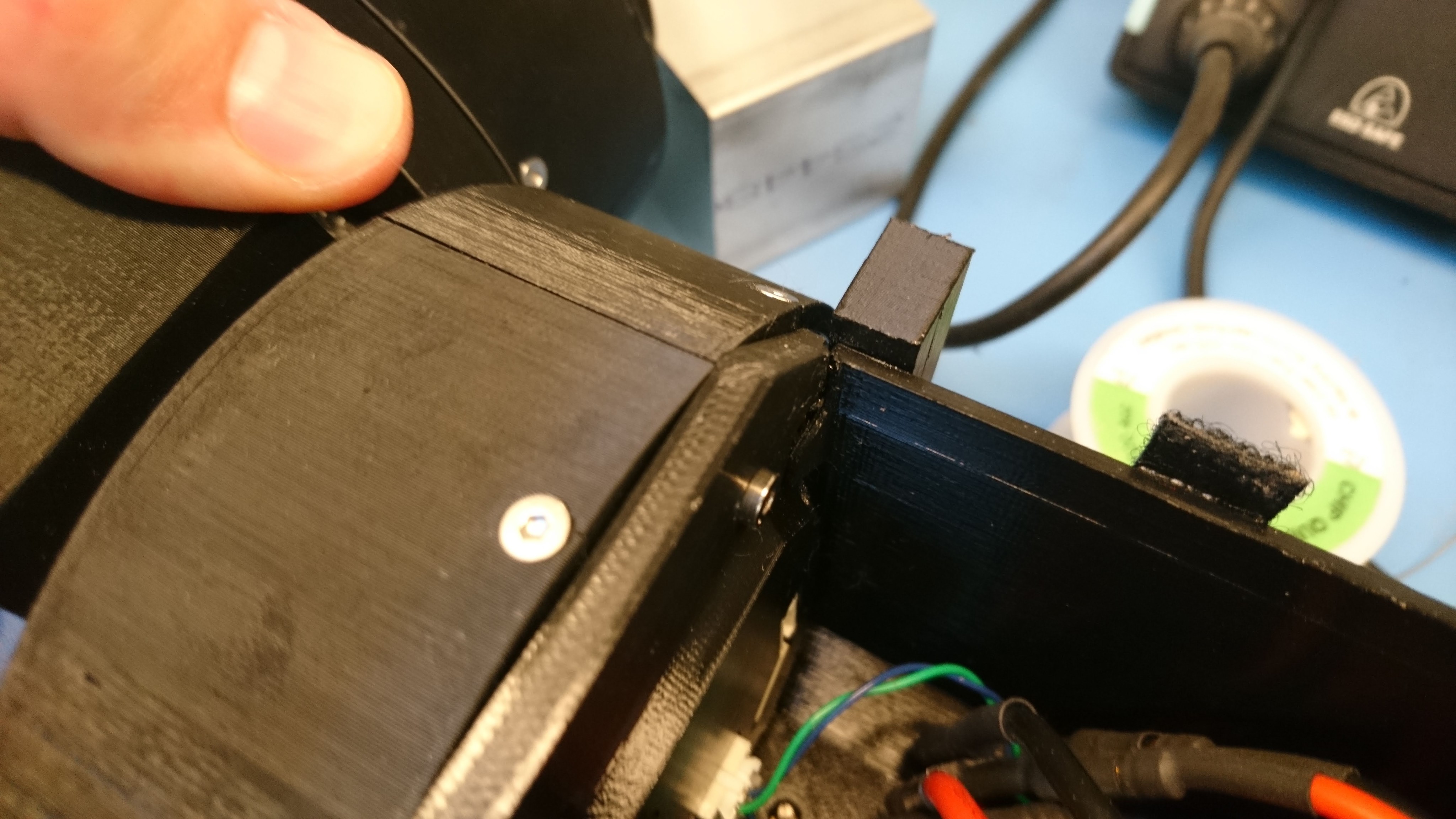
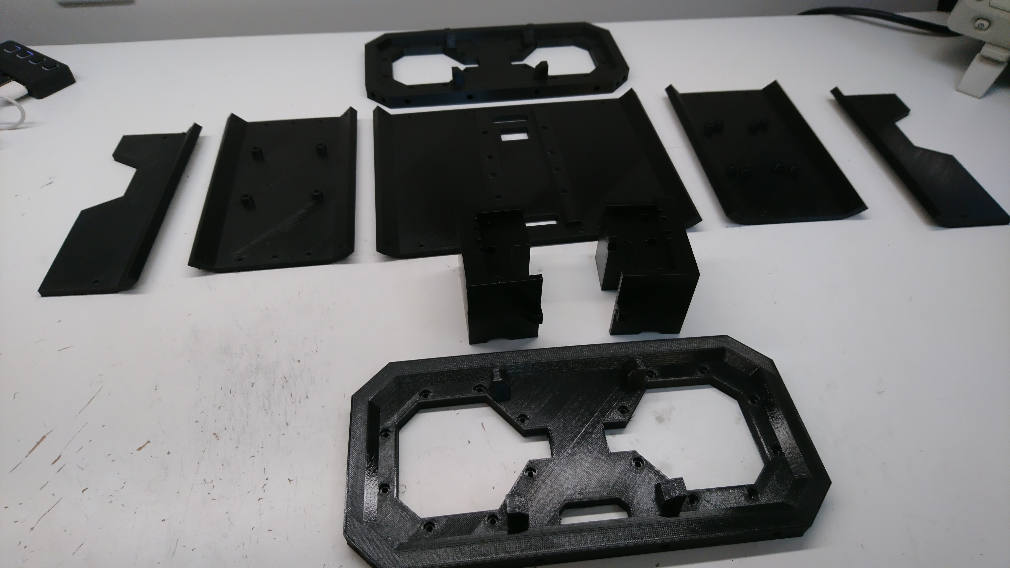
- Robustness: The planet input, outer housing, back housing, and controller cover of the mk1 servo were 3d printed, mostly to save cost and time. This necessitated adding reinforcing rings on the outer housing, as it is nearly impossible to 3d print something with the required material properties in a single print. At this point, all of these components should just be made of aluminum like the others.
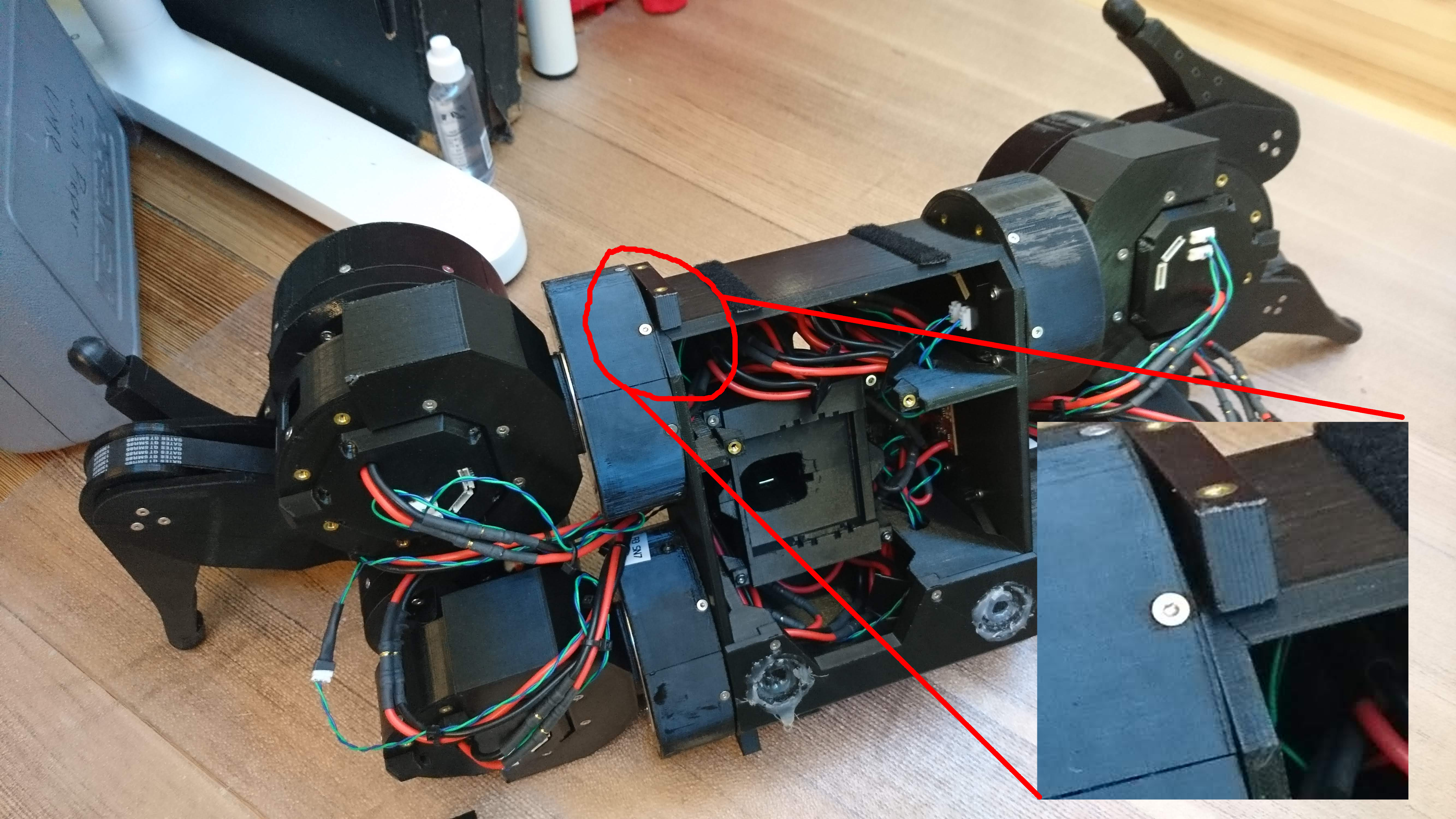
- Repairability: Once the mk1 was assembled, there was no way to disassemble it, as installing the stator interfered with the ability to remove the outer housing, and the outer housing in place interfered with the ability to remove the stator.
- Convenience: The mk1 servo used the r3.1 moteus controller, which had RS485 connectors sticking straight out the back, and bare power wires coming out the back. That orientation for connecting things was not terribly convenient in the full rotation leg design, and required making extension cables. The newer moteus controller has the connectors sticking out the bottom, so the servo needs to accommodate that.
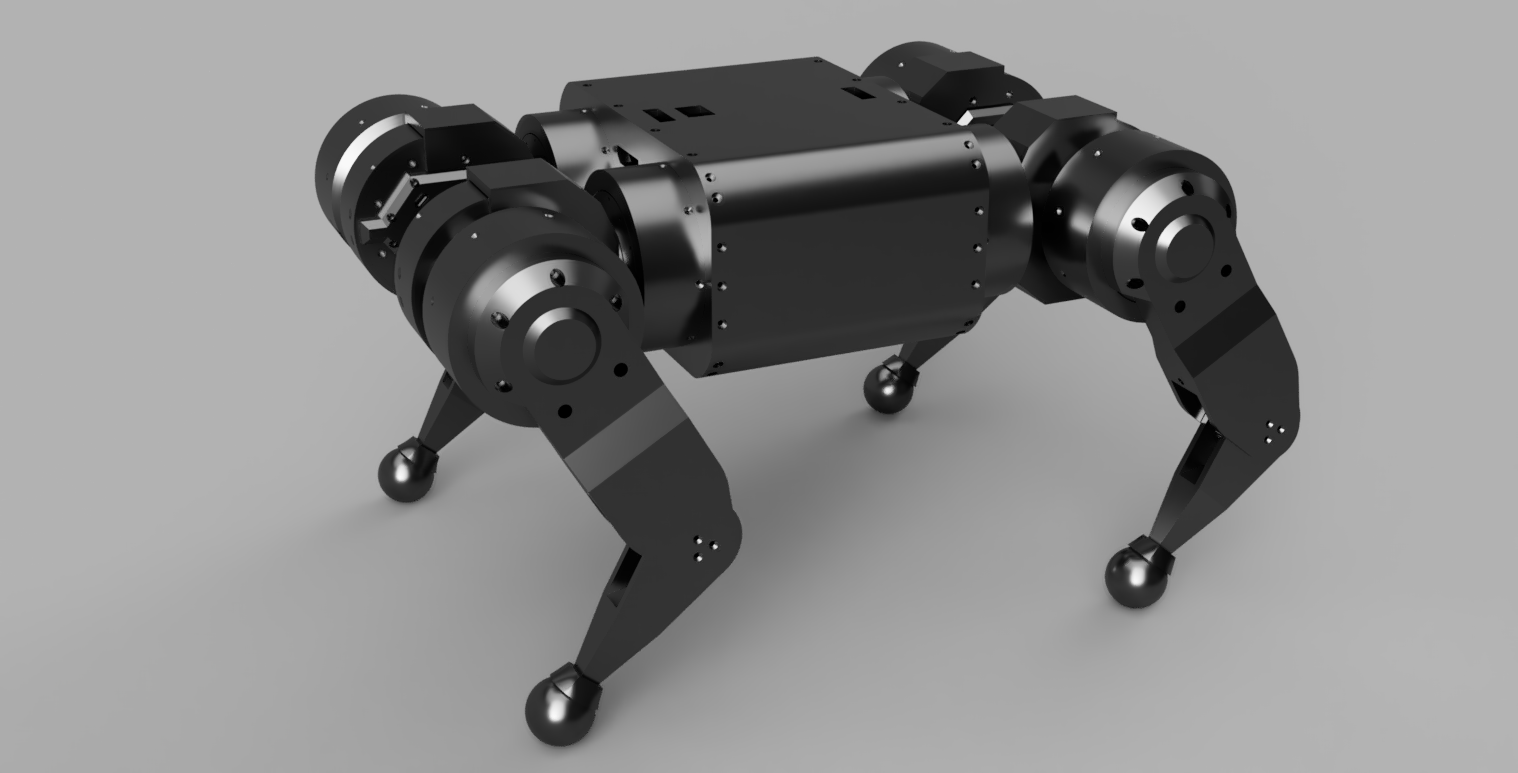
CAD explosion
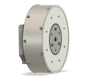
CAD rendering