mjbots November 2020 Update
Here’s the approximately annual giant video update:
If you’re interested in any of the topics in more detail, I’ve collected links to individual posts for each of the referenced items below.
Thanks for all your support in the last year!
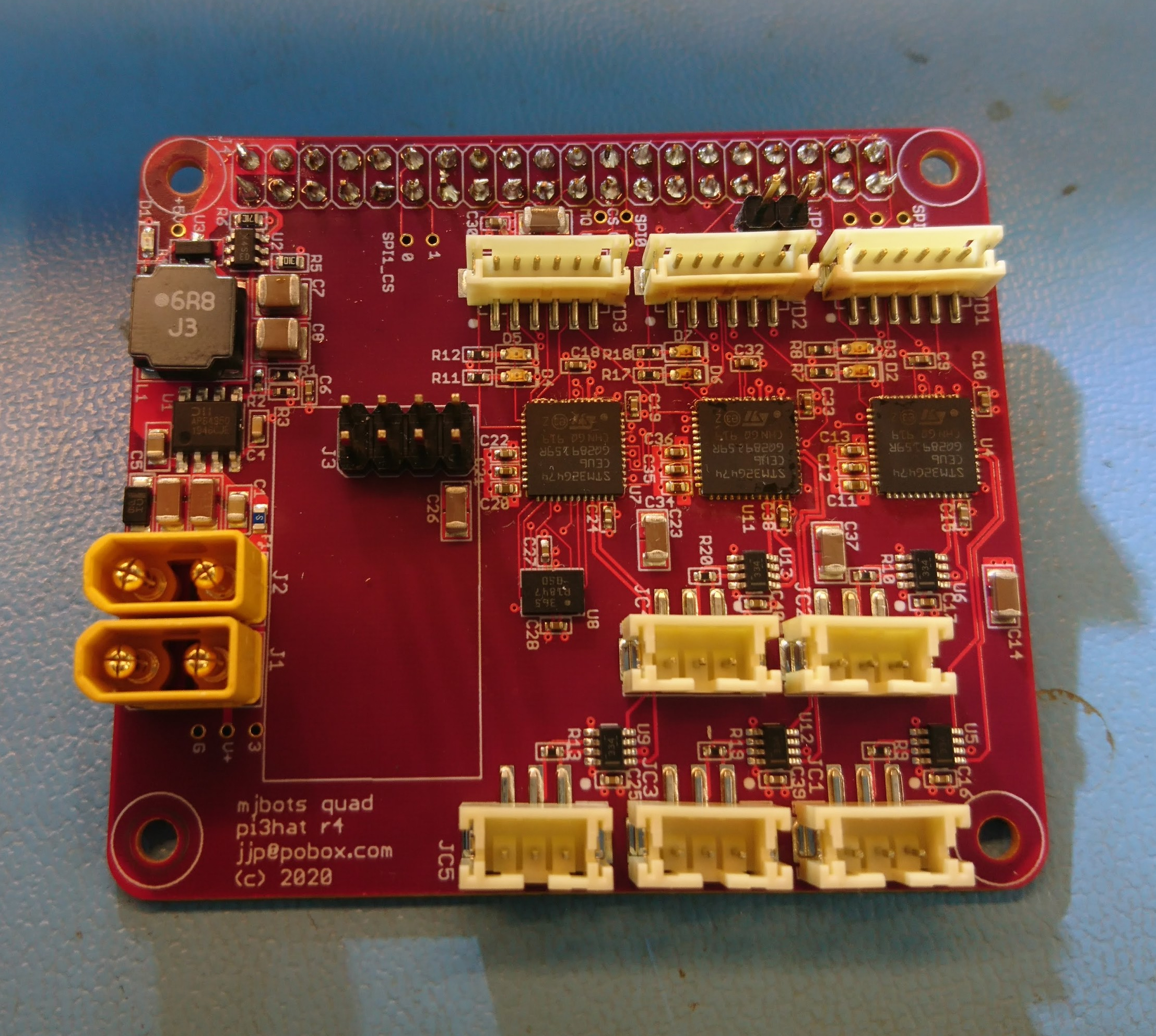
Moteus
Announcement of moteus r4.3: Production moteus controllers are here!