Archives: Quad

Overlaying video on telemetry data with ffmpeg and OpenGL

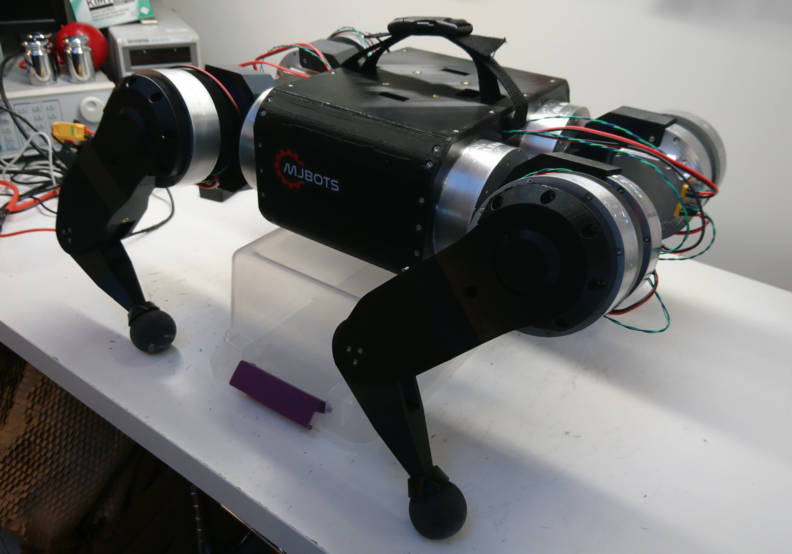
While not its primary purpose, I still plan on entering my walking robots in Mech Warfare events when I can.  In that competition, pilots operate the robots remotely, using FPV video feeds.  I eventually aim to get my inertially stabilized turret working again, and when it is working I would like to be able to overlay the telemetry and targeting information on top of the video.

In our previous incarnation of Super Mega Microbot, we had a simple UI which accomplished that purpose, although it had some limitations.  Being based on gstreamer, it was difficult to integrate with other software.  Rendering things in a performant manner on top was certainly possible, although it was challenging enough that in the end we did nothing but render text as that didn’t require quite the extremes of hoop jumping.  Unfortunately, that meant things like the targeting reticule and other features were just ASCII art carefully positioned on the screen.

Spread spectrum integration

I’ve been developing a new bi-directional spread spectrum radio to command and control the mjbots quad robot.  Here I’ll describe my first integration of the protocol into the robot.

To complete that integration, I took the library I had designed for the nrfusb, and ported it to run on the auxiliary controller of the pi3 hat.  This controller also controls the IMU and an auxiliary CAN-FD bus.  It is connected to one of the SPI buses on the raspberry pi.  Here, it was just a matter of exposing an appropriate SPI protocol that would allow the raspberry pi to receive and transmit packets.

Spread spectrum RF control and telemetry

Now that I have both sides of the nrf24l01+ link covered, it was time to design a protocol to take advantage of them.

Design space

To recap, what I needed was a reliable means of commanding the robot and receiving telemetry, even in congested radio environments.  At competitions or events like Maker Faire, Robogames and such, the wireless environment is often totally trashed.  Hundreds of devices are operating in close proximity, across all spectrum bands, including plenty of things that probably aren’t licensed to be transmitting in the first place.  When we first built Super Mega Microbot, we used a custom protocol with a 5 GHz wifi transmitter as the physical layer and selected USB based dongles which allowed control over the physical layer.  USB proved problematic, and with national RF regulations, it is extremely challenging to find wifi devices which provide that level of control at the RF layer.  Also, even with full physical layer control, wifi is difficult to make work in a reliable manner as there is so much congestion in both the 2.4GHz and 5GHz bands and the channels are so wide.

Resurrected quadruped simulator

Thankfully, I’m now at the point where I’m fixing actual dynamics problems on the robot.  Doubly thankfully I have a robot which is pretty robust and keeps working!  That said, it is still, shall we say, “non-ideal”, to be testing code for the first time ever on a real robot.

Back with my HerkuleX based Super Mega MicroBot, I had a working DART based simulation which was decently accurate.  However, the actuators for that machine were so limited that it didn’t really make sense to do any work in simulation.  The only way to be effective with that machine was to tweak and tweak on the real platform and rely on exactly the right amount of bouncing and wiggling that would get it moving smoothly.

Power distribution board r3

While I was able to make the r2 power distribution board work, it did require quite a bit more than my usual number of blue wires and careful trace cutting.

dsc_0394

Thus I spun a new revision r3, basically just to fix all the blue wires so that I could have some spares without having to worry about the robustness of my hot glue.  While I was at it, I updated the logo:

nrfusb

In order to bring up the final piece of the raspberry pi 3 hat, the nrf24l01+, I wanted a desktop development platform that would allow for system bringup and also be useful as a PC side transmitter.  Thus, the nrfusb:

dsc_0367

Similar to the fdcanusb, it is just an STM32G474 on the USB bus, although this has a pin header for a common nrf24l01+ form factor daughterboard.

The next steps here are to get this working at all, then implement a spread spectrum bidirectional protocol for control and telemetry.

Simple walking gait on the quad A1

After I restructured my control laws to take advantage of high rate force feedback for the pronking experiments, I haven’t actually managed to port the walking gait yet.  Now that I have a brand new robot, it seemed like a good time!

This gait is basically the same thing as I ran on the quad A0 in principle.  The opposing feet are picked up according to a rigid schedule, and moved to a point opposite their “idle” position based on the current movement speed.  Any feet that are completely placed on the ground just move with the inverse of the robot’s velocity.

quad A1: First movement

After getting all the legs swapped out, I ran my existing software to validate that all the pieces worked together.  Here’s a quick video showing basically what I’ve shown before, but with all new hardware:

Building the quad A1

Now that I have a bunch of the mk2 servos set and ready to go, a new leg design, a new power distribution board to power them, and a raspberry pi3 hat to communicate with them, I built a new quadruped!  I’m calling this the mjbots quad A1, since basically everything is upgraded.

dsc_0362

After I initially assembled the new legs onto the chassis, I realized I had the geometry slightly off and there was some interference through part of the shoulder rotation.  I made up new printed parts and replaced everything in front of the camera.  Thus, watch some high speed robot surgery:

Attitude estimation for pi3 hat

Now that the IMU is functioning, my next step is to use that to produce an attitude estimate.  Here, I dusted off my [unscented Kalman filter](http://unscented Kalman filter) based estimator from long ago, and adapted it slightly to run on an STM32.  As before, I used a UKF instead of the more traditional EKF not because of its superior filtering performance, but because of the flexibility it allows with the process and measurement functions.  Unlike the EKF, the UKF is purely numerical, so no derivation of Jacobians is necessary.  It turns out that even an STM32 has plenty of processing power to do this for things like a 7 state attitude filter.