Archives: Qdd100

Gear testing fixtures

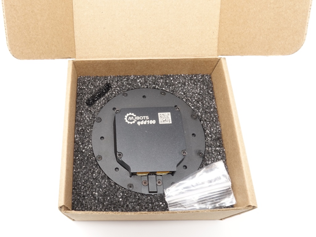
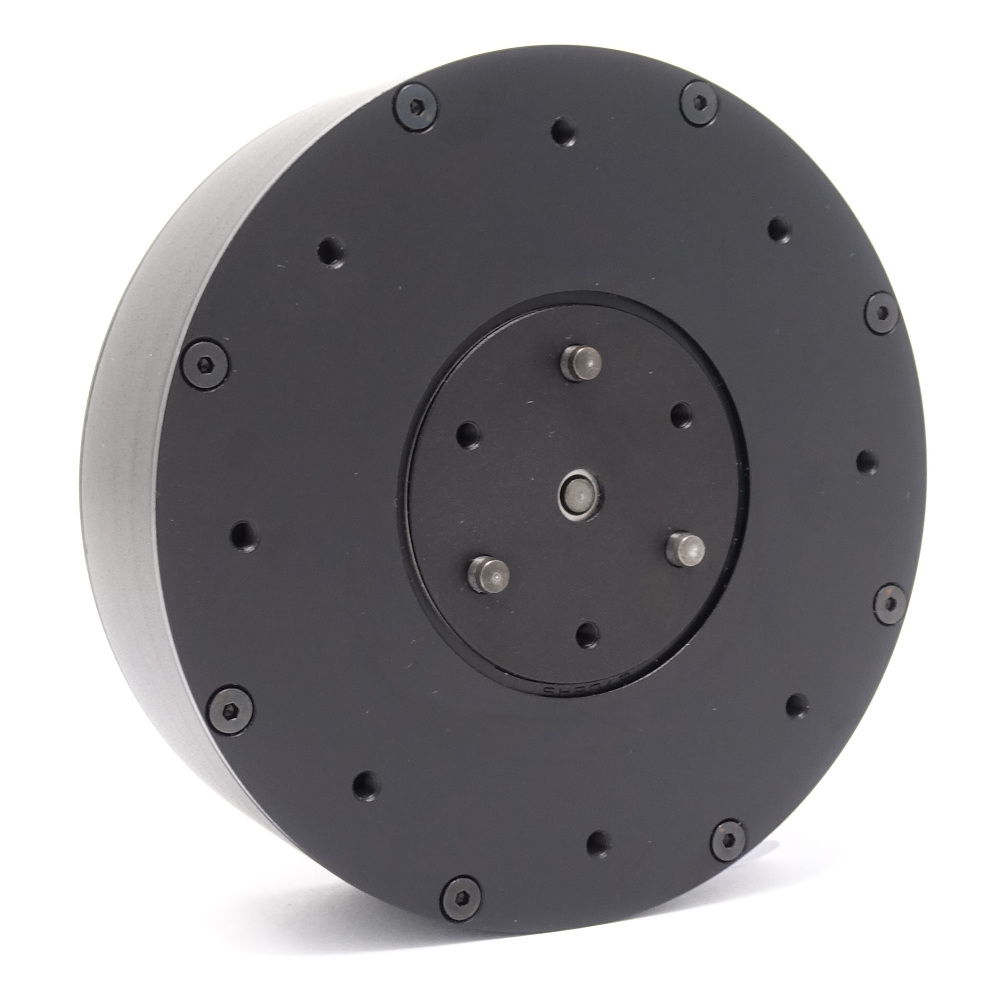
The qdd100 servo uses a planetary geartrain as the transmission reducer. This consists of an outer ring gear, an inner sun gear connected to the rotor as the input, and 3 planets connected to the output. The tolerances of these gears directly impacts the performance of the servo, namely the backlash and noise.

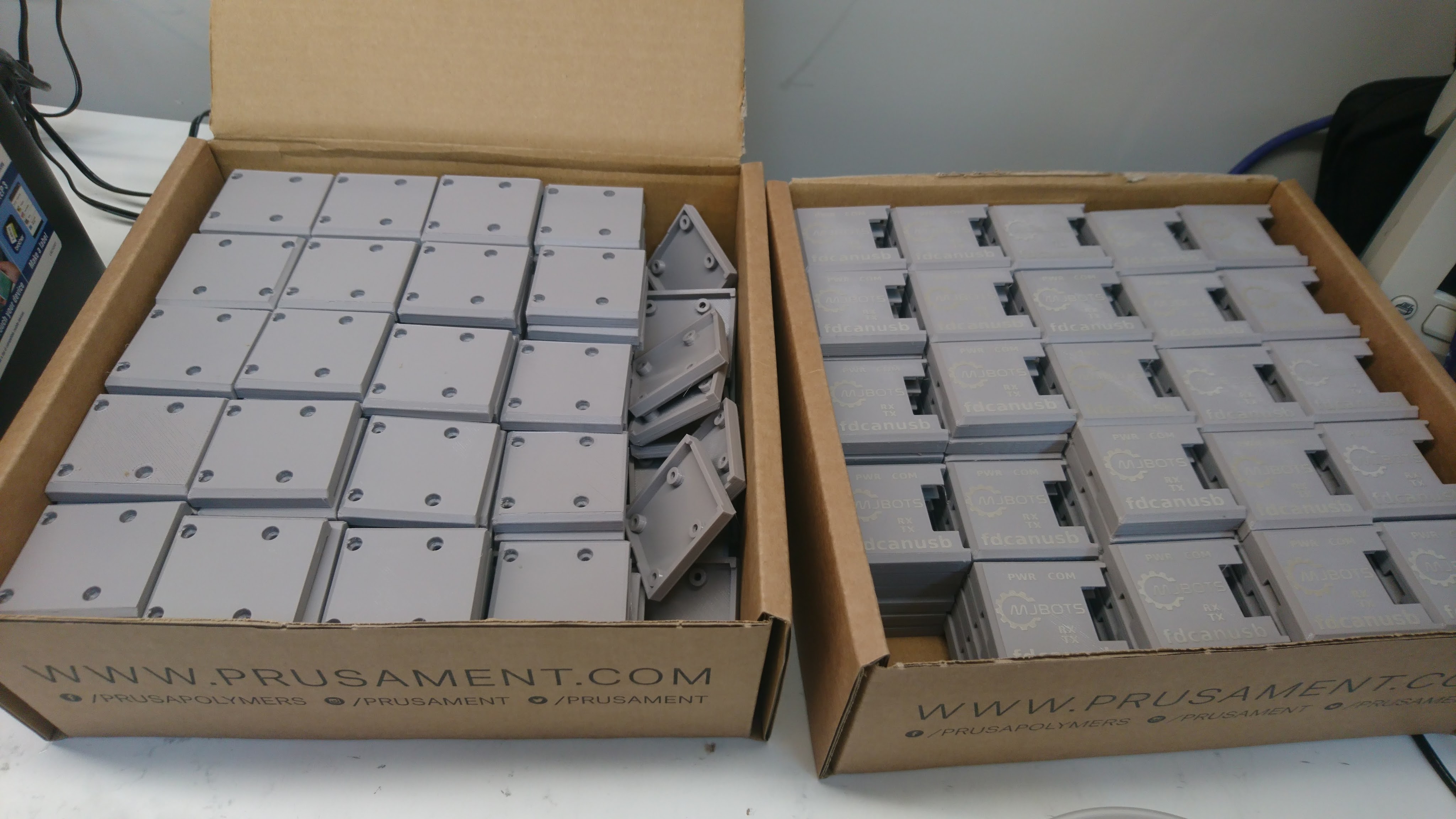
To date, I’ve been hand-binning these and testing each servo for noise at the end of production. To make that process a bit more deterministic, and with less fallout, I’ve built up a series of manual and semi-automated gear metrology fixtures to measure various properties of the gears.

Improved qdd100 packaging

There are a lot of steps necessary to get a product to market, not just a fancy render. I admit to being far from covering all the bases yet, but we’re getting there. In that spirit, I recently upped the packaging game of the qdd100 with some custom boxes and foam inserts. Pick one up at mjbots.com!

qdd100 beta 2

I’d like to introduce the qdd100 beta 2!

This is the newest version of a quasi-direct-drive servo from mjbots. It has a sleek new look, and improved performance all around:

Beta 1 Beta 2
Peak Torque 12.5 Nm 16 Nm
Backlash +- 0.2 degrees +- 0.1 degrees
Voltage Range 10-34V 10-44V
Mass 470g 475g

Comparison from beta 1 to the new beta 2

Additionally, the M3 mounting holes are now 3mm deep instead of the previous 2mm, which gives more flexibility when designing mounts.

Up-rating the qdd100 beta thermal bounds

When I first posted the qdd100 beta on mjbots.com, I performed a simple “continuous torque” test where I measured the torque that could be applied indefinitely without thermal limiting in a lab environment. It has come to my attention that other servos rate their “continuous torque” for a much lower value of “continuous”, sometimes only 30s. To make the situation clearer, I measured the time to thermal limiting at a range of torques and updated the product page.

quad A1 stand-up sequence part N

I’ve worked through a number of different iterations of the stand-up sequence for the quad A1 (2019-05, 2019-09). The version I’ve been using for the last 6 months or so works pretty well, but because it drags the legs along the ground to get them into position, it can have problems when operating on surfaces with a lot of traction, like EVA foam, besides being uselessly noisy.

To make things just a bit more robust, I’ve now tweaked the startup routine so that the shoulders lift legs clear off the ground before positioning the legs, then lowers them back down into place. This makes the stand up routine much more likely to succeed on just about any surface:

Dealing with stator magnetic saturation

In my previous experiments demonstrating torque feedback (full rate inverse dynamics, ground truth torque testing), I’ve glossed over the fact that as the stator approaches magnetic saturation, the linear relationship between torque and current breaks down. Now finally I’ll take at least one step towards allowing moteus to accurately work in the torque domain as motors reach saturation.

Background

The stator in a rotor consists of windings wrapped around usually an iron core. The iron in the core consists of lots of little sub-domains of magnetized material, that normally are randomly oriented resulting in a net zero magnetic field. As current is applied to the windings, those domains line up, greatly magnifying the resulting magnetic field. Eventually most of the sub-domains are aligned, at which point you don’t get any more magnifying effect from the iron core. In this region, the stator is said to be “saturated”. You can read about it in much more depth on wikipedia or with even more detail here. The end result is a curve of magnetic field versus applied current that looks something like this:

Testing qdd100 stator windings

My initial design torque for the qdd100 was a little over 17 Nm. However, when I did my first ground truth torque testing, I found that some servos had a lower maximum torque than I had specified. While working to diagnose those, I built a qdd100 that used an alternate stator winding of 105Kv instead of the 135Kv that are in all the beta units. The Kv rating of a stator describes how fast the motor will spin for a given applied voltage. If you assume the same amount of copper mass of wiring, a lower Kv will mean that there are thinner wires that wrap around the stator more turns (or fewer wires in parallel). A higher Kv will have thicker wires with fewer overall turns.