Archives: Pi3hat

New product Monday: pi3hat

I’ve now got the last custom board from the quad A1 up in the mjbots store for sale, the mjbots pi3 hat for $129.

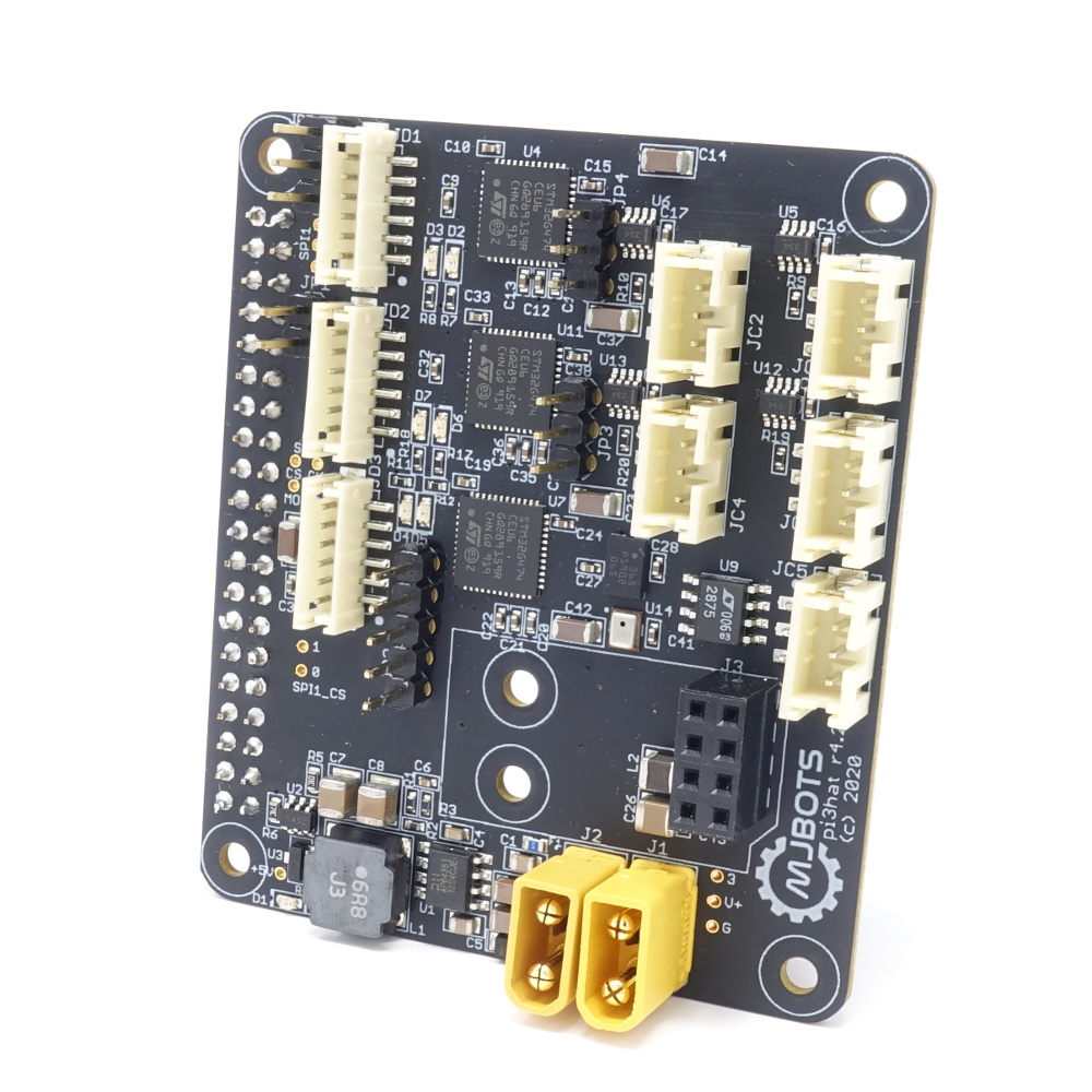
This board breaks out 4x 5Mbps CAN-FD ports, 1 low speed CAN port, a 1kHz IMU and a port for a nrf24l01. Despite its name, it works just fine with the Rasbperry Pi 4 in addition to the 3b+ I have tested with mostly to date. I also have a new user-space library for interfacing with it that I will document in some upcoming posts. That library makes it pretty easy to use in a variety of applications.

Raspberry Pi 4

Only 1 full year after it was released, I managed to get a Raspberry Pi 4 and test it out in the quad A1. I had been delaying doing so because of reports of thermal issues. The Pi 3B+ already ran a little hot and I didn’t want to have to add active cooling into the robot chassis to get it stable.

It looks like the Raspberry Pi engineers have been hard at work because the newer firmware releases have significantly reduced the overall power consumption and thus the thermal load. In my testing so far it only seems “a little” hotter than the 3b+.

Video and telemetry synchronization (diagnostics part 8)

This is part of a continuing series on updated diagnostic tools for the mjbots quad A1 robot.  Previous editions are in 1, 2, 3, 4, 5, 6, and 7.  Here I’ll be looking at one of the last pieces of the puzzle, synchronizing the video with the rest of the telemetry.

As mentioned previously, recording video of a robot running is an easy, cheap, and fast way to provide ground truth information on all of the sensors and actuators.  However, it is only truly useful if it can be accurately synchronized in time to the other telemetry streams for the robot.

Turret active inertial stabilization

This post will be short, because it is just re-implementing the functionality I had in my turrets version 1 and 2, but this time using the raspberry pi as the master controller and two moteus controllers on each gimbal axis.

I have the raspberry pi running the primary control loop at 400Hz.  At each time step it reads the IMU from the pi3 hat, and reads the current state of each servo (although it doesn’t actually use the servo state at the moment).  It then runs a simple PID control loop on each axis, aiming to achieve a desired position and rate, which results in a torque command that is sent to each servo.  Here’s the video proof!

New Mech Warfare turret

Another of the tasks I’ve set for myself with regards to future Mech Warfare competitions is redesigning the turret.  The previous turret I built had some novel technical features, such as active inertial gimbal stabilization and automatic optical target tracking, however it had some problems too.  The biggest one for my purposes now, was that it still used the old RS485 based protocol and not the new CAN-FD based one.  Second, the turret had some dynamic stability and rigidity issues.  The magazine consisted of an aluminum tube sticking out of the top which made the entire thing very top heavy.  The 3d printed fork is the same I one I had made at Shapeways 5 years ago.  It is amazingly flexible in the lateral direction, which results in a lot of undesired oscillation if the base platform isn’t perfectly stable.  I’ve learned a lot about 3d printing and mechanical design in the meantime (but of course still have a seemingly infinite amount more to learn!) and think I can do better.  Finally, cable management between the top and bottom was always challenging.  You want to have a large range of motion, but keeping power and data flowing between the two rotating sections was never easy.