Archives: Pcb

Populating r3.1 moteus controller boards

I am a big fan of MacroFab.  They’ve built a PCB + assembly + more service that is transparent, high quality, and nearly completely self service.  They appear to be making money, so hopefully they will stay in business for some time.

On top of that, they offer a “quick turn” option which gives you populated boards shipped 10 business days after you order them (and I’ve even had them ship out a few days early from time to time)!  The only annoyance is that the quick turn option is limited, as I’ve mentioned before, to boards that meet certain criteria, among them having 20 or fewer items on the bill of materials.  To try and get this first quadruped prototype up and running quickly, I’ve been exclusively relying on quick turn boards, which means making some compromises.  Even after some moderate design sacrifices, I haven’t been able to get the servo controller board to 20 parts.  At the moment it is 23.  Thus, when I received the first big-ish PCB order I’ve made (qty 28), I got to spend a morning populating the remaining 3 components on all 28 boards.

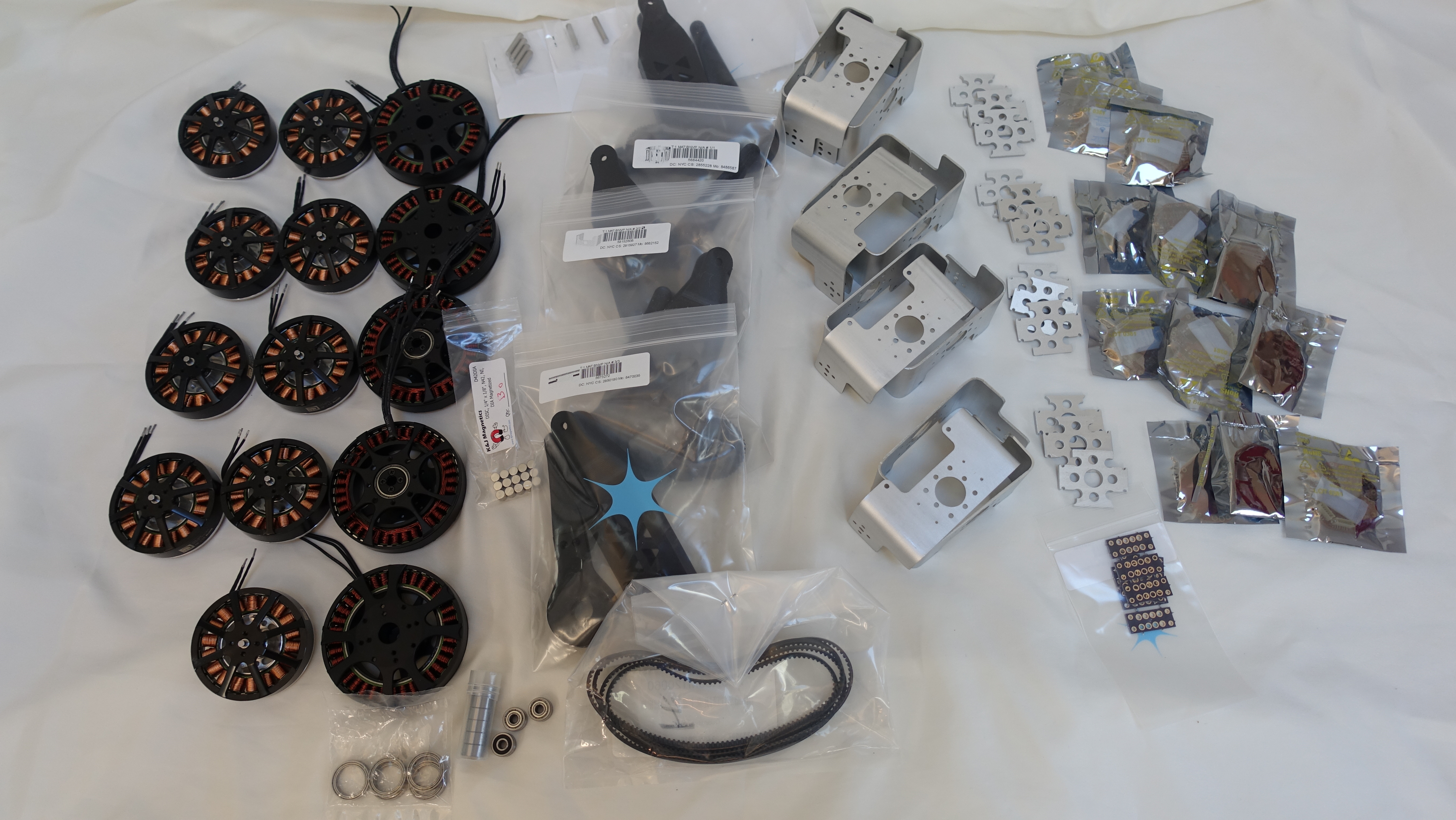
All parts received!

I’ve now managed to get all the custom and long lead time parts in house for the first version of a quadruped based on the new actuators I’ve been designing.

All The Parts!

All The Parts!

That includes all the motors, custom brackets, and at least moderately working versions of all the custom PCBs.  Now I just have to get the local rework done, get the software into a semi-reasonable state, and put it all together!

Quadruped Junction Board

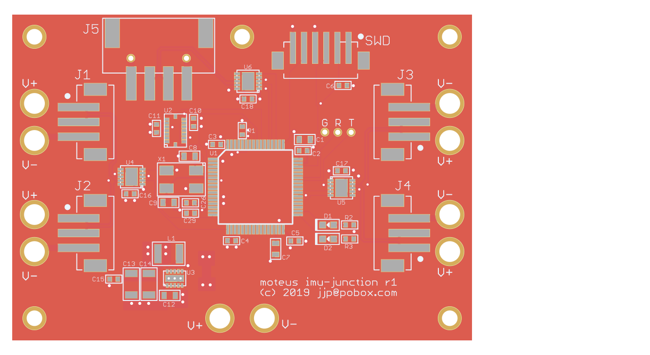
The full quadruped robot needs to both distribute power from the primary battery and RS485 serial network to all 12 servos.  To make the wiring of that easier, I’ve made up a junction board to provide power connectors, distribute the data network, and act as the IMU for when that is necessary.

20190314-moteus-imu-junction-r1.png

The RS485 network is bridged between two halves of the robot.  One connection comes in from the controlling PC and two separate links go out, one for the left side and one for the right side.  This could eventually allow the controller on the junction board to take intelligent actions itself, such as querying the force applied on all 12 servos.  It could then return the result in a single RS485 transaction to the host computer.  I am expecting that will be necessary to achieve closed loop control approaching 1kHz.

My simplest ever PCB

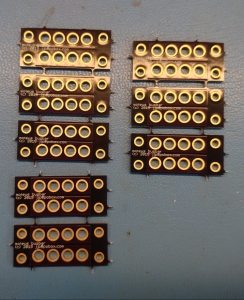
While wiring up the first 3 degree of freedom mammal actuator, I knew I was going to have a need to distribute power to each of the three motor controllers.  Thus, enter my simplest ever PCB.  It is just 4 holes for each of power and ground with traces connecting them.

moteus busbar PCB

moteus busbar PCB

It took an annoying amount of time to actually solder in all the necessary wires, but it was still better than the alternative of a bunch of ring terminals bolted together.

Controller r3 and endurance testing

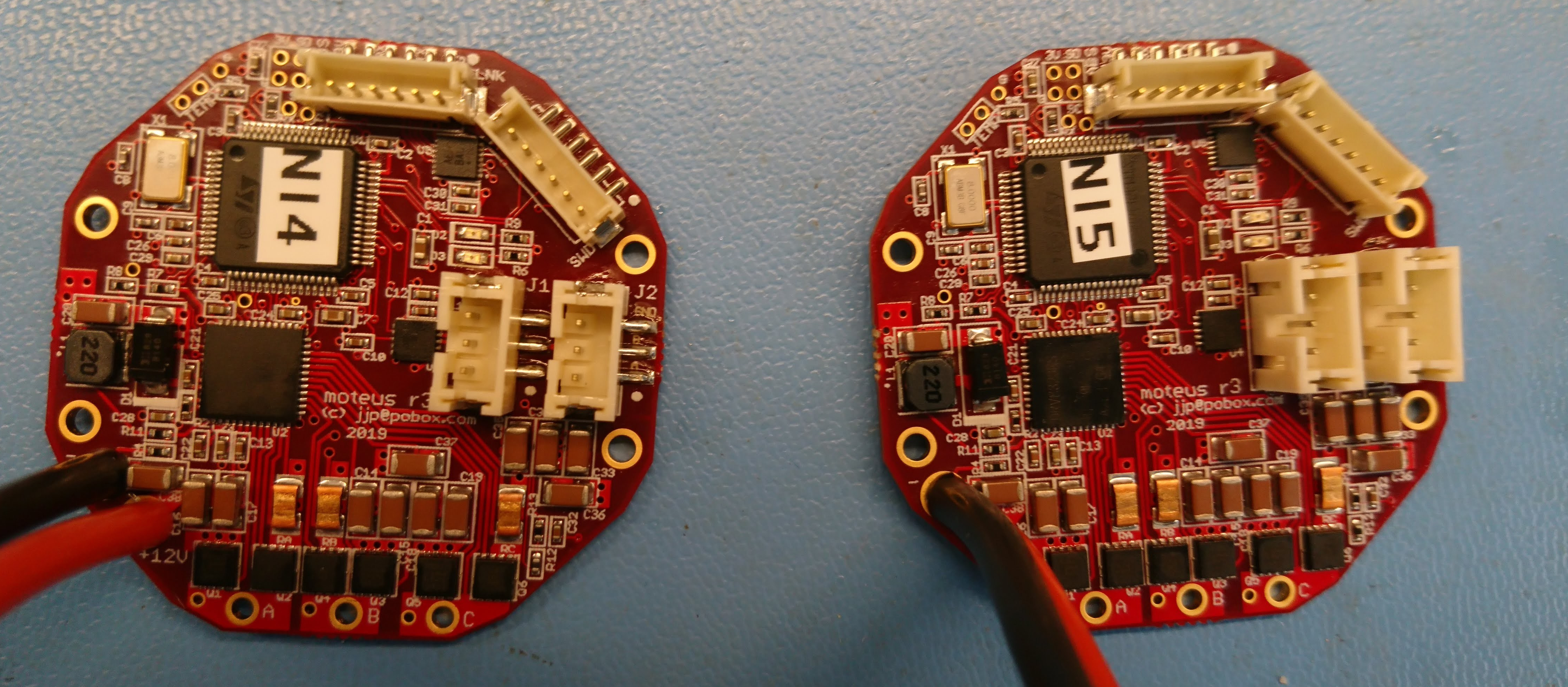
After my self-education on MLCC derating I spun yet another low-volume prototype run of the servo controller.  This one has more than double the effective capacitance by doubling the number of capacitors and by selecting capacitors that have less derating.  I also fixed an incorrect pad geometry for the 6 pin ZH connector, optimized the BOM count a bit and reselected parts that were no longer available.

2x fully assembled controller r3

2x fully assembled controller r3

Motor controller heatsinking

The controllers for the improved actuators for SMMB have a moderate amount of power to deal with.  During jump maneuvers they can put 60 amps of phase current into the motor, and I’ve applied for very short intervals over 500W of power to a motor.  The FETs on the board are relatively high performance, but there is still a fair amount of heat that has to be dissipated.

When getting started, I knew I would likely have to do something to get heat out of the board and had a two stage plan.  The first was to heatsink the back of the controller board and second, if that wasn’t enough, heat sink the front of the board.

Brushless actuator control board, r2

The first revision of the brushless servo control board for SMMB was successful in getting a leg to jump.  I ended up doing a small-run second revision that addressed a few minor problems and added a couple more capabilities.

  • RS422 Debug/Link Port: I had a 3.3V serial port exposed previously for debugging, however it caused my USB-serial converter to dislike itself due to common mode ground shifts and it wasn’t reliable at high baud rates (>3Mbps).  I also wanted to support “linked” modes, where two servos would perform control in the actuator space at full rate.
  • Debug through holes: r1 had a number of debug connections, all of which were unpopulated SMD pads.  I decided that through holes were easier to connect debug wires to.
  • Vertical SWD connector: I had initially thought I would hide the SWD connector within an enclosure.  However, the initial enclosure prototypes made that seem less desirable, so I switched it to vertical.
  • More debugging points: When bringing up the first board, I ended up doing a lot of carefully balancing scope probes on various pins, when there was plenty of board room to just have through hole debug points.  Lesson learned.
  • FET temperature sensing: r1 just had an external temperature sensor port, r2 additionally has a thermistor next to the FETS.

Macrofab’s current pricing scheme provides a great incentive to keep your BOM below 20 parts, as that is the only way to get quick turn service.  Otherwise you pay an extra 2 or 3 weeks of calendar time.  In r1, I went to some lengths to stay under 20, however, it just wasn’t going to work with r2, so I left a few easy-ish or non-critical parts unpopulated to do them myself: the connectors, LEDs, and one really big diode.

HT-18 Thermal Imager Macro Mod

While working on the improved actuators for SMMB, I wanted to be able to perform some quantitative experiments to design the thermal transfer of the controller board and enclosure.  I figured that feeling with my fingers probably wasn’t scientific enough to make consistent progress.

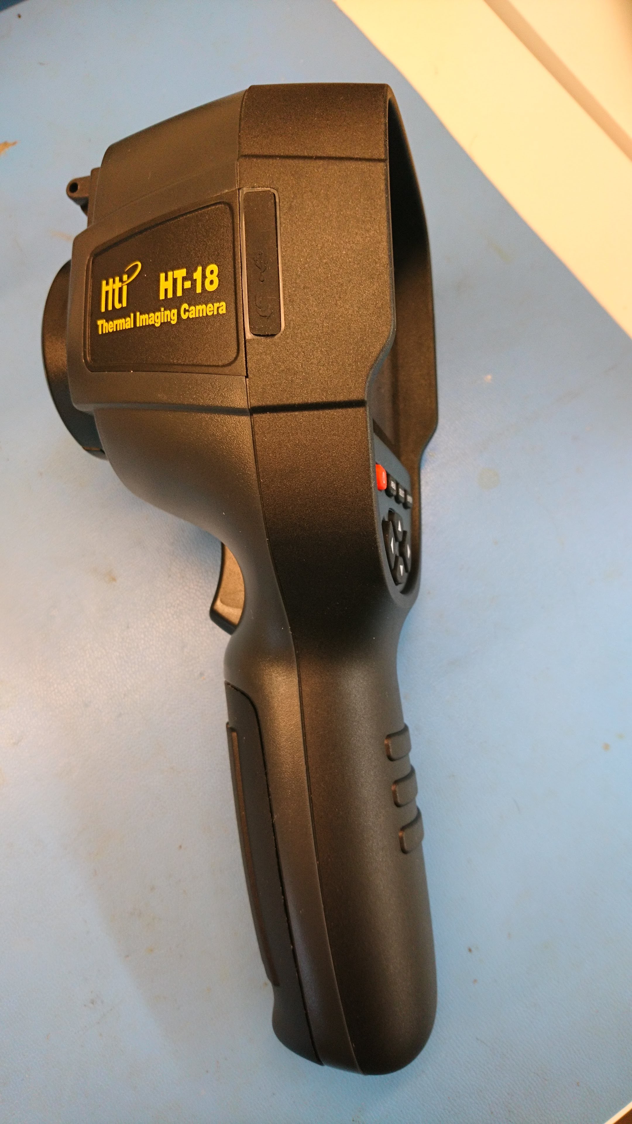
Enter an inexpensive Chinese thermal imager, which you can find for under $300 from time to time.  A non-affiliate Amazon link: https://www.amazon.com/gp/product/B07BDJZ845

HT-18 Thermal Imaging Camera

It has a resolution 220x160, reads up to 300C and being intended for construction inspection has at least a little software support for reading out actual temperatures and capturing images for reports.  The only downside is the focal length.  It really can’t focus on anything less than about a meter away.  That isn’t too great for PCB inspection.