Archives: Pcb

Programming and testing moteus controllers

Like with the fdcanusb, I built a programming and test fixture for the moteus controllers.  The basic setup is similar to the fdcanusb.  I have a raspberry pi with a touchscreen connected via USB to a number of peripherals.  In this case, there is a STM32 programmer, a fdcanusb, and a label printer.  Here though, unlike with the fdcanusb fixture, I wanted to be able to test the drive stage of the controllers and the encoders too.

Power distribution board r3

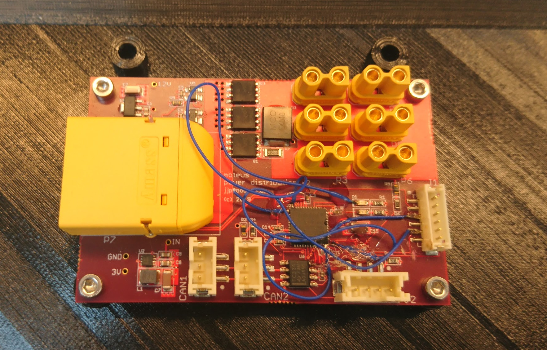
While I was able to make the r2 power distribution board work, it did require quite a bit more than my usual number of blue wires and careful trace cutting.

dsc_0394

Thus I spun a new revision r3, basically just to fix all the blue wires so that I could have some spares without having to worry about the robustness of my hot glue.  While I was at it, I updated the logo:

New quad raspberry pi interface board

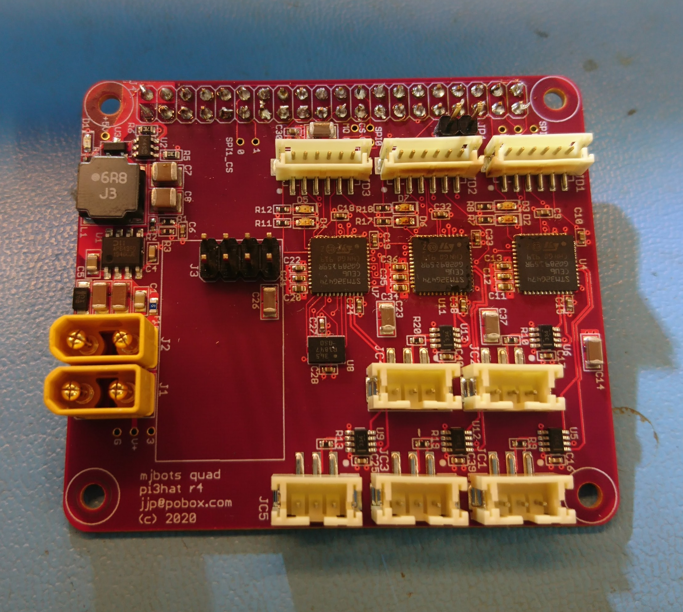
With the new FD-CAN based moteus controllers I need a way for the raspberry pi to communicate with them.  Thus I’ve got a new adapter board in house that I’m bringing up:

dsc_0339

This one has 5 independent FD-CAN channels, an IMU, a port for an nrf2401l RF transceiver as well as a buck converter to power the computer from the main battery bus.

The prototypes were largely constructed by MacroFab, although I did the Amass connectors and the STM32s because supply chain issues prevented me from getting those parts to MacroFab in time.

New quad power distribution board

Finally returning back to other pieces of my quad roadmap, I finished getting an updated power distribution board ready for the quad A0.  This board is one I had made many months ago and mostly brought up, but then didn’t quite finish.  The r1 was when I first discovered my unfortunate stm32g4 pinout problems that doomed 3 of my in flight boards.  The pictures here are of r2, which suffered from yet more pinout problems, resulting in more than my usual number of blue wires.  Fortunately, identifying those problems here let me fix them ahead of time for the fdcanusb and moteus r4 boards.

Moteus controller devkit PCBs in house

Update 2020-01-15: All the development kit slots are full.  Thanks for your interest!

I’ve now received all the supplies I need to make up development kits for the moteus controller and to make a test quadruped!

I’m planning on making a few development kits from this production run so others can experiment with the moteus brushless controllers.  Some people have already expressed interest in getting one – you have hopefully been contacted earlier.  If you are interested in getting an opportunity to buy an early access kit and haven’t heard from me yet, fill out this form!

fdcanusb

One of the necessary pieces for bringing up the moteus brushless controller and for ongoing development with it is being able to communicate with the device on the desk.  There aren’t many options for desktop FDCAN communication currently, and certainly none that are in the affordable range occupied by the [CANUSB family of devices](http://CANUSB family of devices) which I’ve used before and was very happy with.  Thus I created “fdcanusb”, a USB to FDCAN converter that allows one to communicate with FDCAN devices via a USB interface using a documented protocol, no drivers necessary.

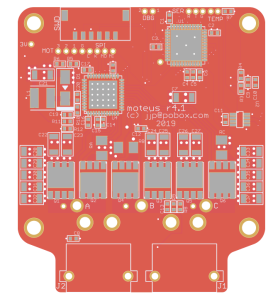
moteus controller r4.1

Another step in my plan for the next revision of the moteus servo mk2, is an updated controller board.  As mentioned in my roadmap, I wanted to revise this board to make improvements in a number of domains:

  • Communications: Now instead of RS485, the primary communications interface is FD-CAN.  This supports data rates of up to 8 Mbit and packet lengths up to 64 bytes.  The header is nominally at the original CAN bit rate, but I have no need to be standards compliant and am running very short busses so I may run everything at the higher rate.
  • Connectors: Now there exist power connectors, in the form of XT30 right angle connectors and they are also daisy chainable like the data connectors.  Additionally, all the connectors exit from the bottom of the board to make routing easier in configurations like the full rotation leg.
  • Controller: This uses the relatively new STM32G4 controller series.  It is lower power than the STM32F4, supports FD-CAN, and also supports closely coupled memory, which may allow me to improve the speed of the primary control loop execution by 3 times.
  • Voltage range: This board now has 40V main FETS, with all other components at 50V rating or higher.  Thus it should be safe with inputs up to 8S (34V or so).
moteus r4.1 rendering

moteus r4.1 rendering

pre-charge circuit

Next up in Super Mega Microbot 2’s existence is being able to run untethered.  Before that can happen, I need to be able to plug in a battery, and hopefully not have everything explode.  As seen with the IMU junction board, even minor inductive links can result in chips getting toasted.  I had thought that just adding sufficient capacitance to each of the point-of-load converters would resolve the issue, but in fact that almost made it worse.

gimbal control board revision

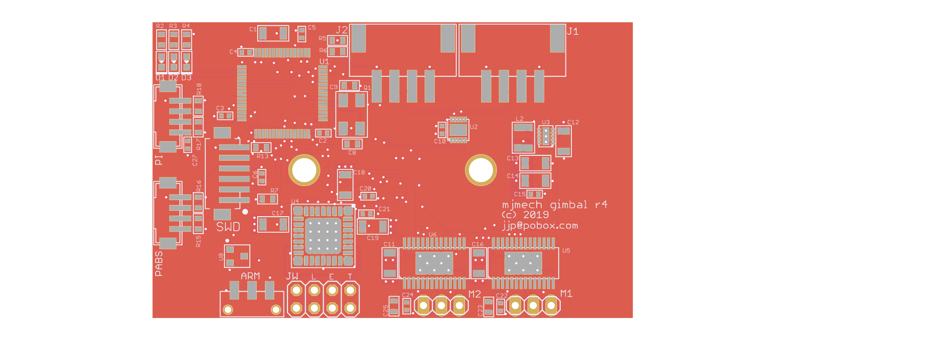
With the new gearbox based mech chassis for Super Mega Microbot 2, the old gimbal controller would need some updates.  It has these new features/capabilities:

  • Higher input voltage: The old system ran at 2S, so 7.2V nominal.  Now we’re running at 5S, so 18.5V nominal.
  • RS485 data: The HerkuleX based robot used TTL level data communications.  moteus uses RS485.
  • Daisy chained power: With the new raspberry pi based computer in the turret, I now need to have an additional power and data port up on the mobile part of the turret.
  • No camera passthrough: Similarly, since the camera is directly attached to the raspberry pi 3, I don’t need to mess with having a connector to pass it through anymore.
PCB rendering

PCB rendering

rpi3 interface board

Now that I have a chassis that can walk a little bit, I need to get the onboard computer working.  To do that, I needed to update the raspberry pi 3 daughterboard I built for the previous turret for the new bus voltage and communication format.

The rpi3’s UART is incapable of controlling the direction line on the RS485 transceiver, so I added a small STM32 micro in line to control the transmit / receive direction.  It adds a little bit of latency, but testing the firmware I was able to get it down to only a byte’s worth or so.