Archives: Pcb

moteus-x1

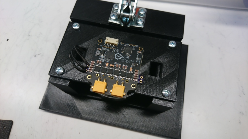
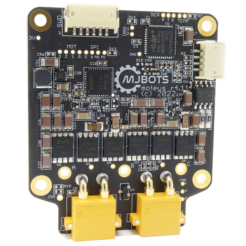
I’m excited to announce the release of the newest moteus motor controller, the moteus-x1!

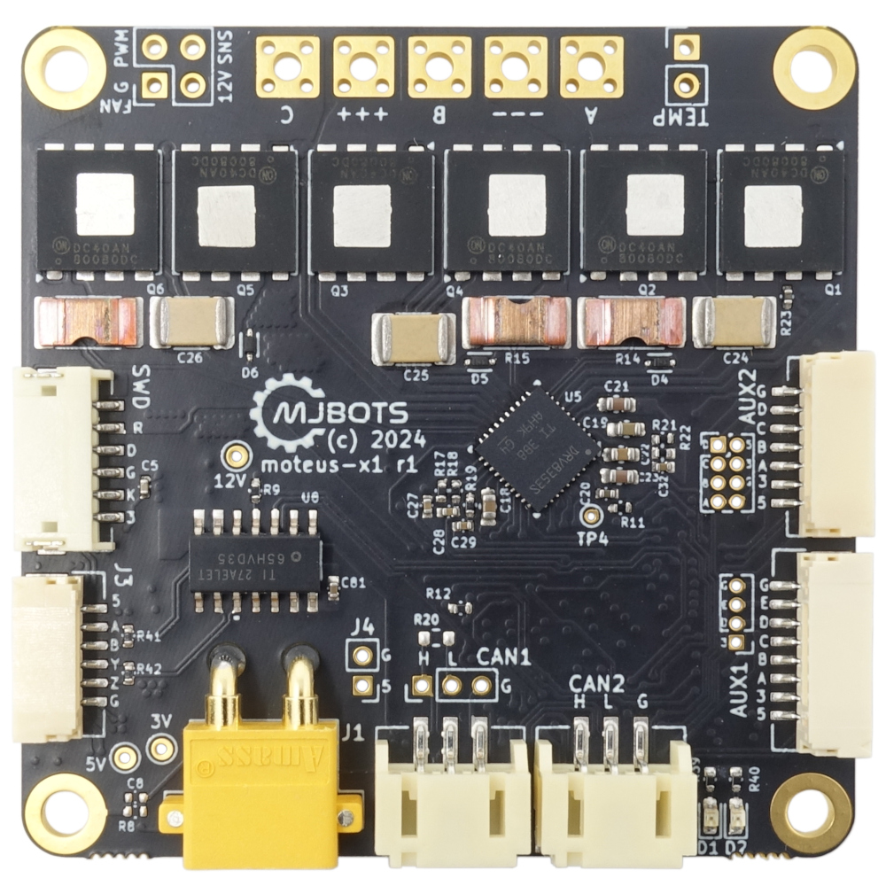
The biggest differences between the moteus-x1 and other moteus controllers is improved output phase current capacity. The x1 is rated for 25A continuous output phase current with no cooling and 60A continuous with fan based cooling. The other big improvement are 12V fan output pads with PWM support. Supporting high power cooling helps the x1 to achieve its higher output current rating.

mjpower-ss

It’s another new product day here at mjbots! Introducing the mjpower-ss:

This provides many of the same functions as the power_dist r4.5b:

  • Pre-charge: High capacitance, low-impedance loads up to 4000uF will be safely turned on in a controlled manner.

  • Undervoltage and overcurrent protection: If the instantaneous current exceeds 100A, a soft circuit breaker is engaged.

  • Connector multiplexing: 1x XT90 input feeds 6x XT30 output connectors which are wired in parallel.

  • External switch: An external illuminated switch is supported, with the same connector and pinout as for the power_dist. A switch harness can be purchased separately.

5 Side PCB Test Fixture

If you look around online, there are lots of examples of PCB test fixtures used to perform end of line testing. In the low to medium volume scale, nearly all of these are either clamshell or 2 side affairs, where probe pogo pins or interfaces are connected to the bottom and top of the board.

When developing the moteus-n1, one of the challenges was the number of right angle board edge connectors it has. Those right angle connectors are what allow it to maintain a very low overall stack height when installed in applications, but are also much harder to perform testing on, since by definition the access points are not vertical. On the base n1, there are 6 total right angle connectors, 2 on each of 3 sides, and future variants may have additional bottom side CAN and power connectors populated to make 8 total right angle connectors.

power_dist r4.5b

Here is yet another new product announcement! In the same line as the new pi3hat, here is a new minor revision of the power_dist, the r4.5b:

The changes are largely the same as for the new pi3hat:

  • The input voltage range is extended from 10-44V, to 10-54V.

  • The CAN-FD port has +-58V bus fault protection, up from +-12V.

  • Additionally, the measurement noise of the output current has been improved from 300mA to approximately 30mA.

pi3hat r4.5

I’m excited to announce a minor upgrade to the mjbots pi3hat product line, the pi3hat r4.5!

This has a few upgrades over the old r4.4b:

  • The input voltage range is expanded from 8-44V to 8-54V.

  • All CAN-FD ports have +-58V bus fault protection, up from +-12V.

  • 0.1" pin headers are present for the Raspberry Pi I2C, UART, and for 3.3V and 5V outputs

Check it out at mjbots.com today!

Updated moteus test fixture

I documented the first test fixture I built for moteus some time ago. As the shipment volumes have gone up, the fixture became something of a limitation, and also was a little problematic in a few ways.

The old “state of the art”

First, it relied on attaching 3 connectors by hand for each test, which was a decent fraction of the cycle time. Second, the pogo pins it used were non-replaceable, and also connected only to the debug phase wire test vias, which were tiny. They wore out relatively quickly, and replacing them required building a whole new board. Finally, since the pogo pins were PCB mounted, a PCB needed to be printed for any change in the pin locations or which pins to probe.

moteus r4.11

Here’s yet another update to the moteus line, moteus r4.11!

r4.11 is electrically, mechanically, and software compatible with r4.3, r4.5, and r4.8.

This revision supports two alternate footprints for the CAN-FD transceiver to better support component availability and refines the power stage for the DRV8353 gate driver. moteus r4.8 was the first version to use the DRV8353 because of, once again, component availability issues. However, it was developed on a very abbreviated schedule. With r4.11 the EMI is much improved over r4.8 and r4.5, and the efficiency is much better than r4.8 at all input voltages and PWM frequencies.

power_dist load test circuit

While testing some variants and new versions of the power_dist board, I wanted to be able to simulate the types of loads that it experiences with a fully loaded robot. Some things are easy, like this capacitor attached to an XT30 connector:

I also have giant power resistors in a similar form factor:

However, a dumb load resistor isn’t a particularly representative load. Most likely, the loads that a power_dist will drive are active loads with switching regulators. When the output voltage is lower, the current will be correspondingly higher. That is especially important when validating pre-charge behavior, because it means that the current is much higher during the initial pre-charge window than it would be for a pure resistive load.

moteus r4.5

Meet the newest revision of the moteus controller!

Yes, it does look mostly the same as the r4.3 that has been getting a lot of use lately. This revision exists mostly to improve manufacturability, but I snuck in a minor design improvement while at it. Now, the maximum voltage input is rated up to 44V from the 34V of the r4.3! (Note though, that the pi3hat and power_dist still are limited to 34V). Otherwise the new controller is fully electrically, mechanically, and software compatible with the r4.3.

More MLCC learning

It seems that I’m learning much about PCB design the very hard way.  Back last year I wrote up my discovery of MLCC bias derating.  Now I’ll share some of my experiences with MLCC cracking on the first production moteus controllers.

When I was first putting the production moteus controllers through their test and programming sequence, I observed a failure mode that I had yet to have observe in my career (which admittedly doesn’t include much board manufacturing).  When applying voltage, I got a spark and puff of magic smoke from near one of the DC link capacitors on the left hand side.  In the first batch of 40 I programmed, a full 20% failed in this way, some at 24V, and a few more at a 38V test.  I initially thought the problem might have been an etching issue resulting in voltage breakdown between a via and an internal ground plane, but after examining the results under the microscope and conferring with MacroFab determined the most likely cause was cracking of the MLCCs during PCB depanelization.