Compensating for FET turn-on time
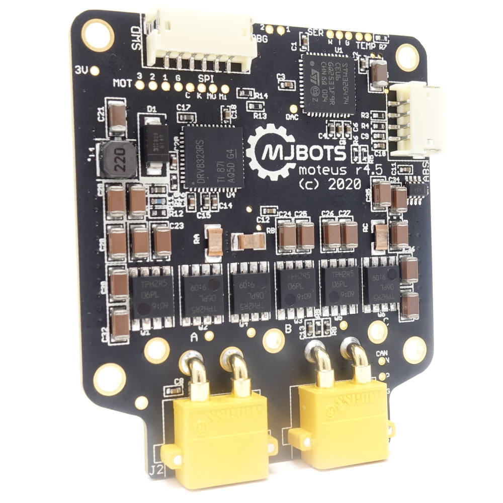
A motor driver like moteus switches power to the phases of a brushless motor using a set of 6 (or possibly more), MOSFETs. The typical topology involves 3 high side N channel MOSFETs and 3 low side N channel MOSFETs arranged in 3 half bridges like this:
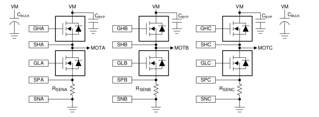
(example 3 half-bridge from DRV8353 reference manual)
Since the gates of these FETs need to be driven with potentially high voltages, and you never want the high side and low side to be on at the same time, typically a gate driver is used. For the moteus r4.5 and earlier controllers, the DRV8323 driver from Texas Instruments is what performs this function. This driver lets you configure the drive current for each of the gates for both operations, charging up the gate and discharging it. For high power drive systems, charging up or discharging the gate too fast can result in undesired transients like accidentally switching the other FET on due to capacitive coupling, or inductive ringing as the current starts moving through the FET instead of the body diode. If the gate charges too slowly, then the FET spends much of its time not fully on, which increases power dissipation in the FETs.