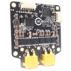
Meet the newest revision of the moteus controller!
Yes, it does look mostly the same as the r4.3 that has been getting a lot of use lately. This revision exists mostly to improve manufacturability, but I snuck in a minor design improvement while at it. Now, the maximum voltage input is rated up to 44V from the 34V of the r4.3! (Note though, that the pi3hat and power_dist still are limited to 34V). Otherwise the new controller is fully electrically, mechanically, and software compatible with the r4.3.
The moteus controller has always supported multiple turns when counting positions. It has a one-revolution magnetic encoder built in, but after turn on, it keeps track of how many turns have occurred. However, if you’ve followed previous moteus tutorials, you have probably noticed a persistent caveat that for accurate control, the position of the output shaft needs to stay within a hundred revolutions of 0.0 or so. Now, I’ll describe why that was, and what I’ve done to remove the limitation, allowing unlimited rotations!
At the request of @nichols in discord, I’ve recently implemented a new control mode in the moteus controller, “stay within”. In this mode, as long as the controller is inside the currently commanded bounds, only a feedforward torque is commanded. When either of the optional lower or upper bound is violated, the normal PID controller is used to force the position back to the bound.
Here’s a quick video demo:
Note that this could have been roughly accomplished in a couple of ways by a higher level controller – either by monitoring the position and commanding zero kp/kd scales when inside the boundary, or just solely commanding feedforward torques based on position sensing. However, this approach lets the control run at the full 40kHz of the moteus controller, which results in much smoother operation at the boundary condition.
The moteus controller uses a DRV8323 smart driver IC to drive the power MOSFETs as well as provide various safety functions. One of the capabilities it has which has so far been unexplored in moteus is its ability to control the drive strength and dead time through software configuration.
In a switching power supply or switching motor inverter, MOSFETs are arranged in a half bridge configuration. Depending upon the type of converter, one or more half bridges are used (3 phase inverters like moteus use 3 of them). Each “half bridge” has two MOSFETs, one connected between positive power and the output terminal, and the other connected between the output terminal and ground.
This release has a number of minor improvements in the host tools (for which there continue to be no distributed binaries, you get to build from source). The biggest improvement in the firmware is the improved low-torque operation as documented here and here. If you have any questions or want help upgrading, hop into discord at #moteus and ask!
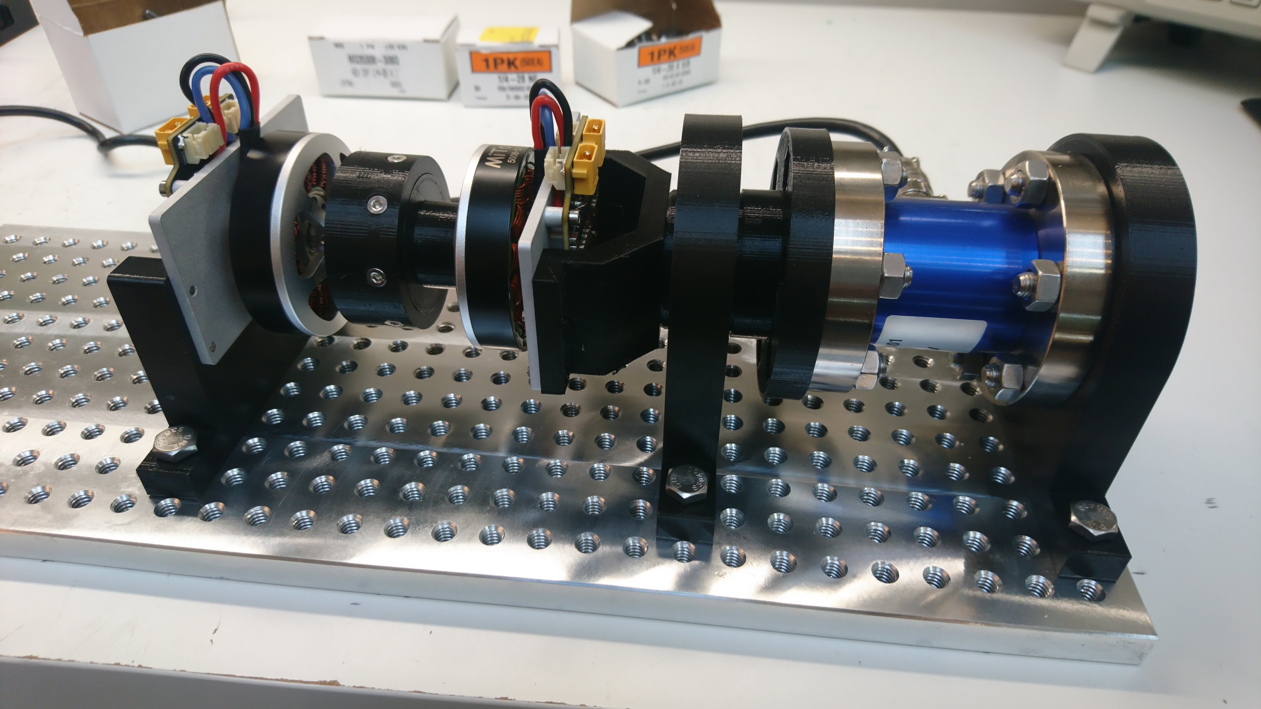
Recently I described some changes I made to improve the low speed torque ripple of the moteus controlle. I also built a dynamometer. I decided to use the dynamometer to quantify how much things had improved with the torque ripple, and to see how much room for improvement was left with any anti-cogging implementation.
Dynamometer script
Here, the test script is relatively simple. I have the “fixture” controller sweep at a very low velocity (0.01Hz) through a bit more than one full revolution using a relatively high I term in the PID controller to ensure that it really holds that position no matter what external torque is applied. Then, the “device under test” controller is just commanded either to be powered off, or in position mode with a pd gain of 0 and a feedforward torque. Then I can just measure the result from the torque transducer while this sweeps through a full revolution, and correlate the measured torque with the encoder position.
Recently dlickindorf pointed out in the mjbots discord that he was having problems with very low torques on his large PMSM hobby-grade motor. While moteus doesn’t have any anti-cogging support yet, it should still be capable of driving motors such that the unexpected torque isn’t much worse than the baseline cogging torque of the motor. However, he was seeing much worse behavior with controlling to 0 current, as much as a full percent of the maximum torque of the motor.
The moteus controller, uses an absolute magnetic encoder to sense the position of the rotor and thus be capable of field oriented control FOC of brushless motors. To date, all the iterations of the controller have used the AS5047P encoder from ams. This is relatively common, works fine over SPI and hasn’t caused any problems. While investigating some other issues, I decided to take a stab at trying some alternate encoders. First, I tried the AS5047U, which is the same basic encoder, but incorporates a digital filter. I also tried the MA732, from Monolithic Power, which uses a different operating principle and also includes a digital filter. The plus side of the MA732 is that it reports full 16 bit values, even if not all of them provide a lot of value.
This has the torque transducer on one end, coupled to the “fixture” moteus controller through a bearing support. Then that is connected via a 3d printed coupler to the “device under test” moteus controller, which is hard mounted to the base plate. Any net torque between the two controllers will be coupled back to the transducer resulting in a measured torque.