moteus firmware release 2022-07-11
It has been on github for a few days now, but I’m excited to announce the newest moteus firmware release, 2022-07-11. This release includes some big features, and some quality of life improvements all around.
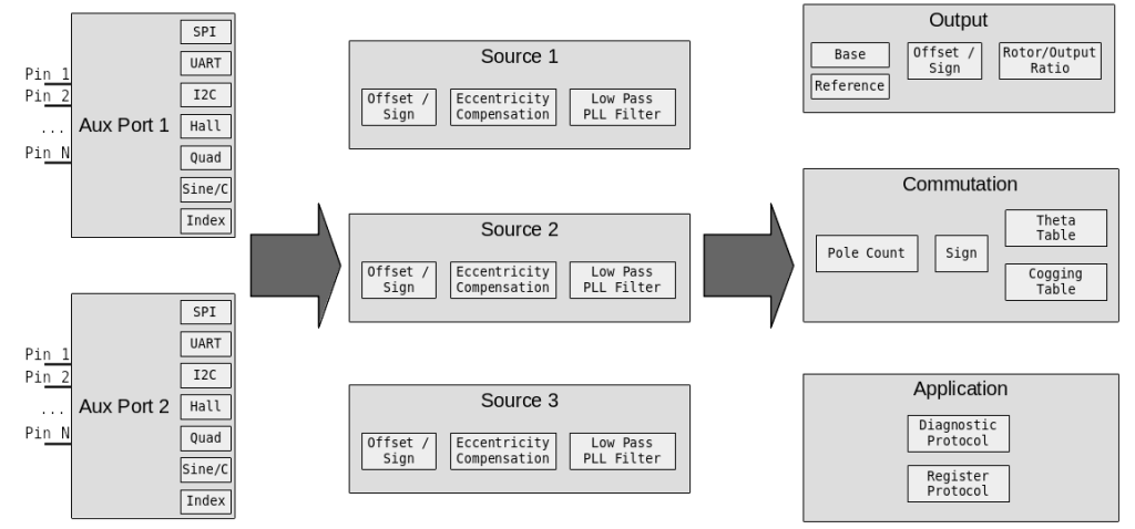
- Flexible I/O subsystem: This release includes the new flexible I/O subsystem. This adds support for many new encoder types and lets you connect them up in a wide variety of ways.
- Cogging torque compensation: Preliminary support for cogging torque compensation is present in this release. It works pretty well on a number of motor types already, future articles will describe it in more detail.
- Encoder eccentricity compensation: This feature lets you linearize the output position and velocity in the face of non-linear encoder readings. A write-up for it is also forthcoming in the not-too-distant-future.
- Transparent no-BRS CAN-FD communication: If your CAN-FD network is only capable of operating at 1Mbps, and you send queries frames with BRS turned off, moteus will now respond in kind. This eliminates most needs to change the CAN bus frequency due to marginal electrical properties.
This is an exciting time for moteus, and the new features will keep coming!