Archives: Moteus

Moaar power!

Exciting news! All the existing moteus controllers in the world now have an upgraded default maximum power and upgraded rated maximum power as of release 2025-03-27! Depending upon the input voltage and PWM rate, sometimes nearly twice the amount. First, check out the comparison table, then the rationale:

Old default max / rated New default & rated
moteus-r4 340W / 450W 900W <= 30V, 400W >= 38V
moteus-c1 75W / 100W 250W <= 28V, 150W >= 41V
moteus-n1 340W / 1200W 2kW <= 36V, 1kW >= 44V

Background, why a power limit?

moteus brushless motor controllers drive 3 phase PMSM motors, accepting a DC input voltage, and outputting current to each of the 3 phases of the motor. It does so using MOSFET based switching, which alternately connects each phase to either ground, or the DC positive input. As that switching progresses, charge is either drawn, or replenished into, the onboard bulk capacitors.

Configuring an off-axis MA600 encoder with moteus

This is the final post (hah! for now at least) in my series about implementing support for off-axis encoders in moteus (see previous iterations here: 1, 2, 3, 4, 5). In this one, I’ll share the recipe for how to set up an off-axis MA600 encoder using a ring magnet as the only encoder source.

Hardware

Parts list:

Magnet mounting: The ring magnet needs to be rigidly affixed to the rotor of the motor being driven. It may be necessary to construct a bracket to mount the magnet, or a fixture to position the magnet before using an adhesive.

Nonlinear encoder compensation with no reference

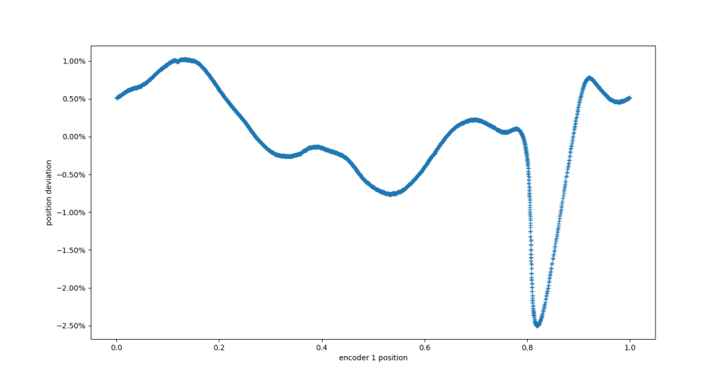
This post is part of series examining how low-cost off-axis encoders can be incorporated into a moteus controlled motor system. For the history, see the previous entries: part 1, part 2, part 3, and part 4. We left off after having tuned the bias current trimming of the MA600 in order provide output from the encoder itself. When compared against a reference AksIM-2, that left an error profile that looks like:

Position error with respect to AksIM-2 after BCT tuning

Position error with respect to AksIM-2 after BCT tuning

Characterizing the MA600 off axis performance and tuning BCT

In previous iterations of this series (see part 1, part 2, and part 3), I built a breakout board for the MA600 TMR encoder and mounted it in an off axis configuration with a diametrically magnetized 32mm OD ring magnet along with a reference AksIM-2 encoder to compare against. Now we can finally get to the part where we can start looking at what the reported values look like.

For my first experiments, I set up a moteus-n1 with the AksIM-2 as the primary encoder, and the MA600 in motor_position.sources.1 in a slot that was not used for anything. Having done that, I plotted the difference in reported angle between the MA600 and the AksIM-2 through a full revolution below, using the compensate_encoder.py script that is now in the moteus repo in reference mode.

Mounting the RLS 32mm ring magnet to a GL80 motor

I’ve been exploring how to add low cost off-axis encoder support into moteus, see part 1, and part 2. In this part, I’ll look at a magnet and how to get it installed on the test motor.

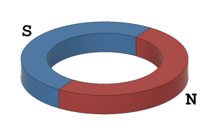
To start, this method of operation will require a diametrically magnetized ring magnet, i.e. one where the axis of magnetization is through the diameter rather than through its depth.

That is not a terribly common magnet configuration, but there are some vendors. For this experiment, I used a 32mm OD ring magnet from RLS that is intended for use with their Orbis line of encoders, part number BM220C320A1ABA00. The motor I am using for this test is a T-Motor GL80, which has a hollow shaft. To mate the magnet to the motor, I 3d printed a fixture (purple) which slipped over the bearing surfaces of the GL80 (pink), and captured the magnet (red).

MA600 / MA732 breakout board

In the previous post, I outlined a possible path to low cost off-axis encoders to be used with the moteus line of brushless controllers. The first step I took was to try and build a minimally sized breakout board that could be used with the MA732/MA702/MA600 line of hall effect angle sensors. You can get these off the shelf, for instance from tinymovr, but I wanted to see if I could make something a bit more compact, and that had the chip close to a board edge so that it could be used for off axis applications.

Low cost off axis encoders for moteus - a beginning

The moteus line of brushless controllers all have an integrated “on-axis” magnetic encoder. These encoders are designed to allow moteus to sense the position of a motor’s shaft directly, assuming that an appropriate diametrically magnetized sense magnet is attached to the rotating shaft and the moteus is mounted so that its sensor is positioned over the magnet.

This works great for many applications, but what about hollow shaft motors? moteus supports a few encoder types that will work for off axis encoders, most notably is the AksIM-2. This is a high performance off-axis encoder that gives great performance and is manufactured in configurations for a variety of hollow shaft diameters. However, it does have downsides. First, it comes with a commensurate price tag. In single quantities, the AksIM-2 and magnetic code disc are more expensive than an entire moteus brushless motor controller. Second, only the moteus-n1 has the necessary RS422 transceiver integrated into it. All other moteus boards need an external RS422 transceiver.

MA600 encoder support in moteus

It’s time to announce support for yet another encoder type in moteus, this time the MA600 precision tunnel magnetoresistance (TMR) sensor. Compared to hall effect magnet angular sensors the MA600 has lower noise and less non-linearity. It has a SPI interface and operates from 3.3V. When used with moteus, it can be connected to AUX2 on moteus-c1 and moteus-n1, and to AUX1/ENC on moteus-c1, moteus-n1, and moteus-r4. Support is available in firmware version 2024-10-29 and newer.

On axis performance

To show what it is capable of, I mounted a small breakout board above an on-axis magnet attached to a mj5208.

Space vector pulse width modulation (SVPWM) for moteus

A permanent magnet motor controller like moteus has to, at the end of the day, apply voltages to the phase wires of a motor in order to induce currents. Those currents generate magnetic fields that push against permanent magnets in the rotor to make the motor move. I’ve looked at parts of this process before, see “Compensating for FET turn-on time”, but in this post we’ll look at an additional technique that can extend the effective modulation depth, thus increasing the maximum speed that a motor can be driven.

PWM output with moteus

Here’s a bit more in-depth discussion of a yet another new feature from moteus firmware release 2024-10-29: pulse width modulated output on auxiliary ports.

A pulse width modulated signal is a logic level signal of a fixed frequency, where the duty cycle, or width of the pulse, is changed or modulated to communicate a scalar value. Obligatory Wikipedia diagram below:

The new feature does what it claims to do, in that a subset of auxiliary pins can now be configured to output a PWM signal. If so configured, the duty cycle can be controlled using either the diagnostic or register protocol.