Development of next-gen power_dist (part 1)
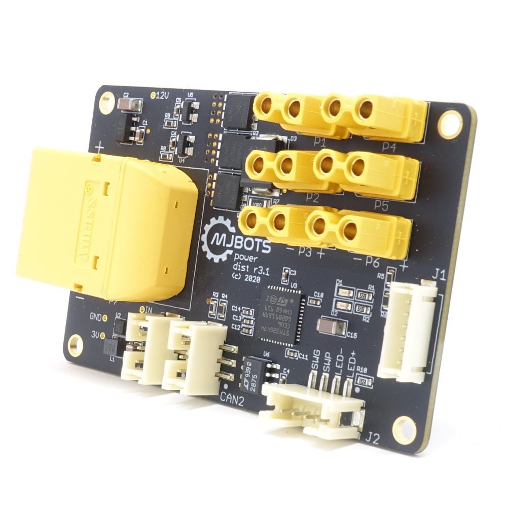
The current iteration of the mjbots power_dist board released back in the summer of 2020 is pretty useful. It pre-charges the input, provides a soft switch, and gives you a bunch of output connectors to make wiring easier.
r3.1 Limitations
However, this version did have some limitations and potential problems. The first is that the pre-charge method it uses, a simple on/off pre-charge resistor, is unable to support a wide range of supply voltages. Either the resistor has a low value, in which case large input voltages will cause thermal failure, or for larger values, it isn’t able to actually pre-charge the bus sufficiently before engaging the primary MOSFET.