Filtering encoder values in moteus
TLDR: moteus can now filter the encoder, resulting in less audible noise. Use firmware version 2021-04-20 and ‘pip3 install moteus’ version 0.3.19, then re-calibrate to get the benefits.
Background
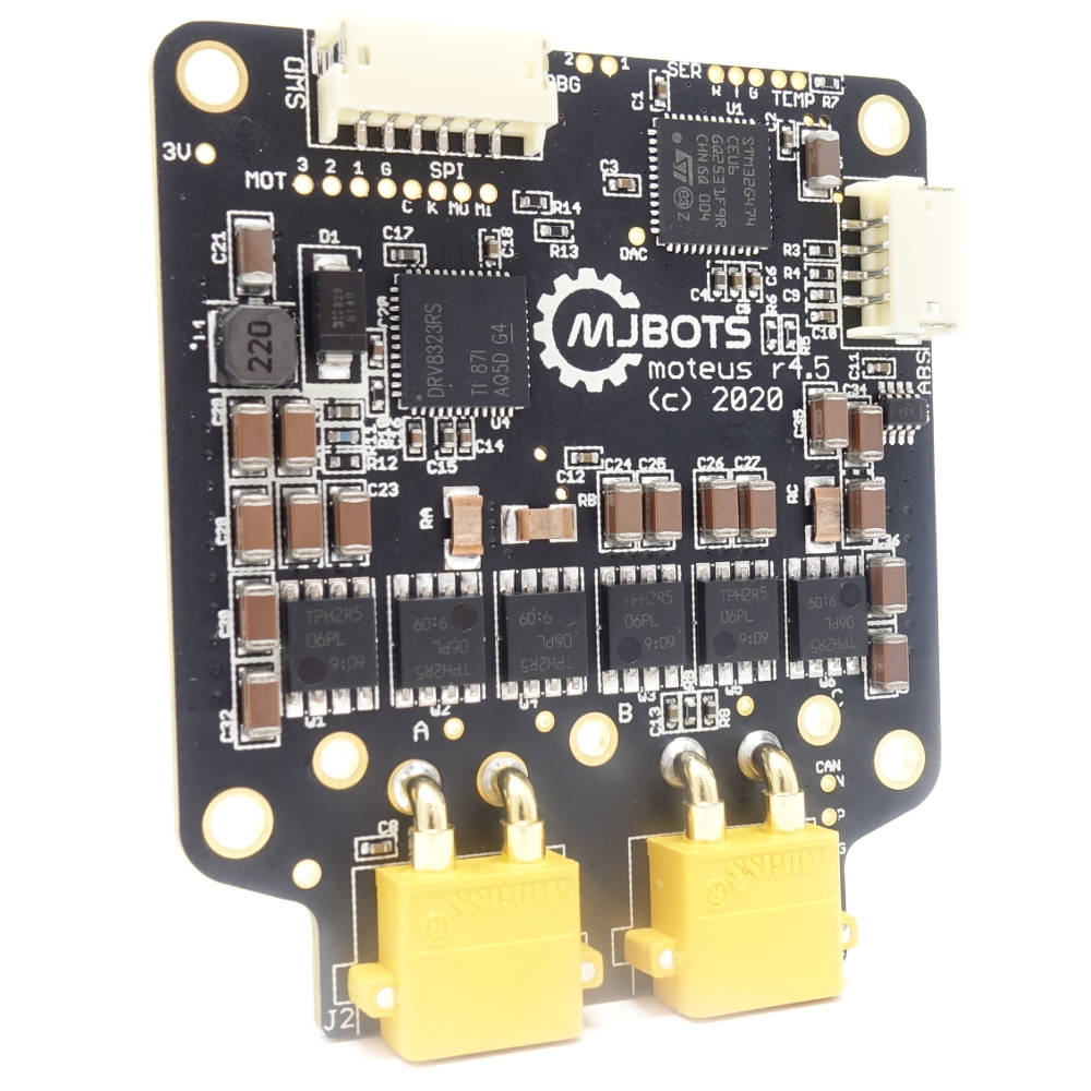
The moteus controller uses an absolute magnetic encoder to measure the position of the rotor. It uses this knowledge to accurately control the current through the three phases of a brushless motor so that the desired torque is produced, i.e. “field oriented control”. This works well, but has some downsides. One, is that magnetic encoders work by sensing the magnetic field produced by a “sensing magnet” that is somehow affixed to the rotor. This sensing process always introduces some noise, so that the sensed rotor position is never perfect.