quad A1 leg experiment: part 3
Yet another in the series on building a new leg for the quad A1:
Yet another in the series on building a new leg for the quad A1:
In the spirit of my last post on the topic, here is another video-only update on a new leg design for the quad A1:
I’m going to try something new for this effort, and instead of making a bunch of blog posts culminating in a video, I’m going to make a bunch of intermediate progress videos. They may, but may not, culminate in an overview blog post. Here’s the first!
Now that I finally have tplot2 working sufficiently to diagnose problems in 3D, it is time to start actually fixing those problems. The first obvious thing I noticed when watching data replay was that the legs scooted around a lot after making contact with the ground. Absent 3D visualization, I knew something was wrong, but couldn’t easily tell what.
Once I was able to plot the commanded position and velocity trajectory, I could clearly see a number of problems. For one, the trajectory was not terribly achievable. The velocity jumped in a discontinuous manner between different phases of the swing cycle, which resulted in large tracking errors when moving the physical legs:
The quad A1 was the first robot I built with foam cast feet. When I did the first feet, I jury rigged a fixture from some old toilet paper rolls to hold things in place while they were curing. When I went to rebuild with my most recent leg geometry, I figured it was time to get at least a little more serious. Thus, my new leg casting fixture:
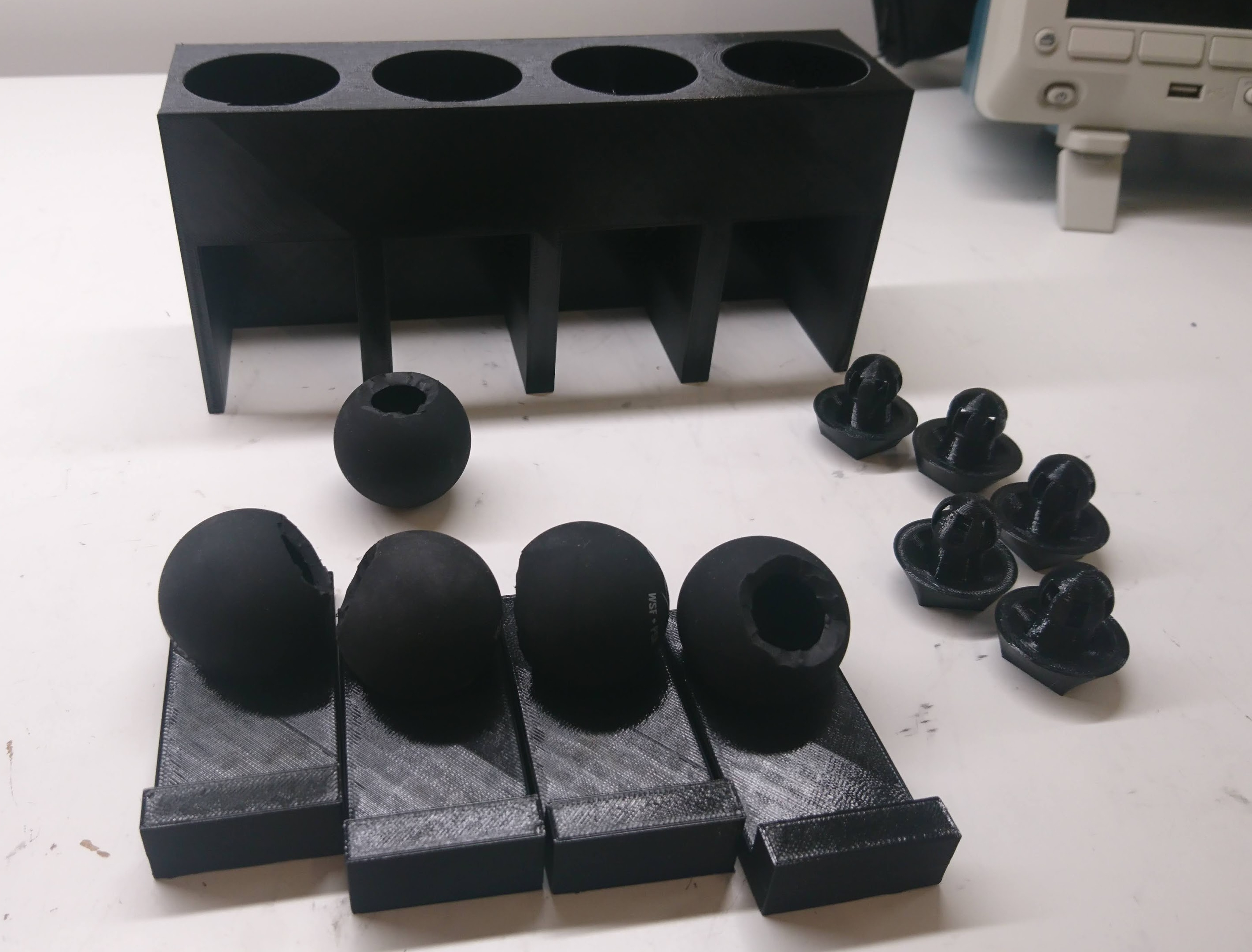
When an insert is cast into place, it is set on one of the trays, the tray is inserted into a slot, and then a weight can be placed on top and constrained by the fixture.
As part of provisioning a quad A1, or anytime the mechanical configuration has been changed, I need to go and record where the zero position of all the joints is. The “0” position for the software now is with the shoulders perfectly horizontal, and the upper and lower leg sticking straight down.
Up until now, every time I’ve done this it has just been by eyeballing and with lots of foam and bubble wrap to shim things into place long enough to record the level. Sometimes I had to go back and try a few times, as even determining when something is straight is not, well, straightforward.
When I first designed the full rotation leg, I didn’t fully appreciate the importance of torque in the knee joint. Despite the fact that my first force based IK showed that when the legs are immediately under the body, the knee joint carries the entire load of the robot, I still managed to not add any reduction there.
The initial design used a 1:1 ratio, because that allowed me to use the same single piece 3d printed gear design I had used before. A 28 tooth gear with 5mm pitch resulted in a gear that was larger than the output plate on the qdd100 servo, so it could just be bolted directly on. To work with a smaller number of teeth, I had to split the gear into two parts, connected by pins, as the gear is now smaller than the qdd100 output plate.
After casting the feet, the final step was to join the lower leg with the 3d printed foot bracket. This I just did with some slow cure epoxy.
It seems strong enough for now, I was able to manually apply 10kg of load to a single leg while perfectly horizontal with no signs of stress, which should be good enough for a 4g 4 legged jump.
All the legs (and a spare) are now assembled with belts and a lower pulley ready to go on a robot!
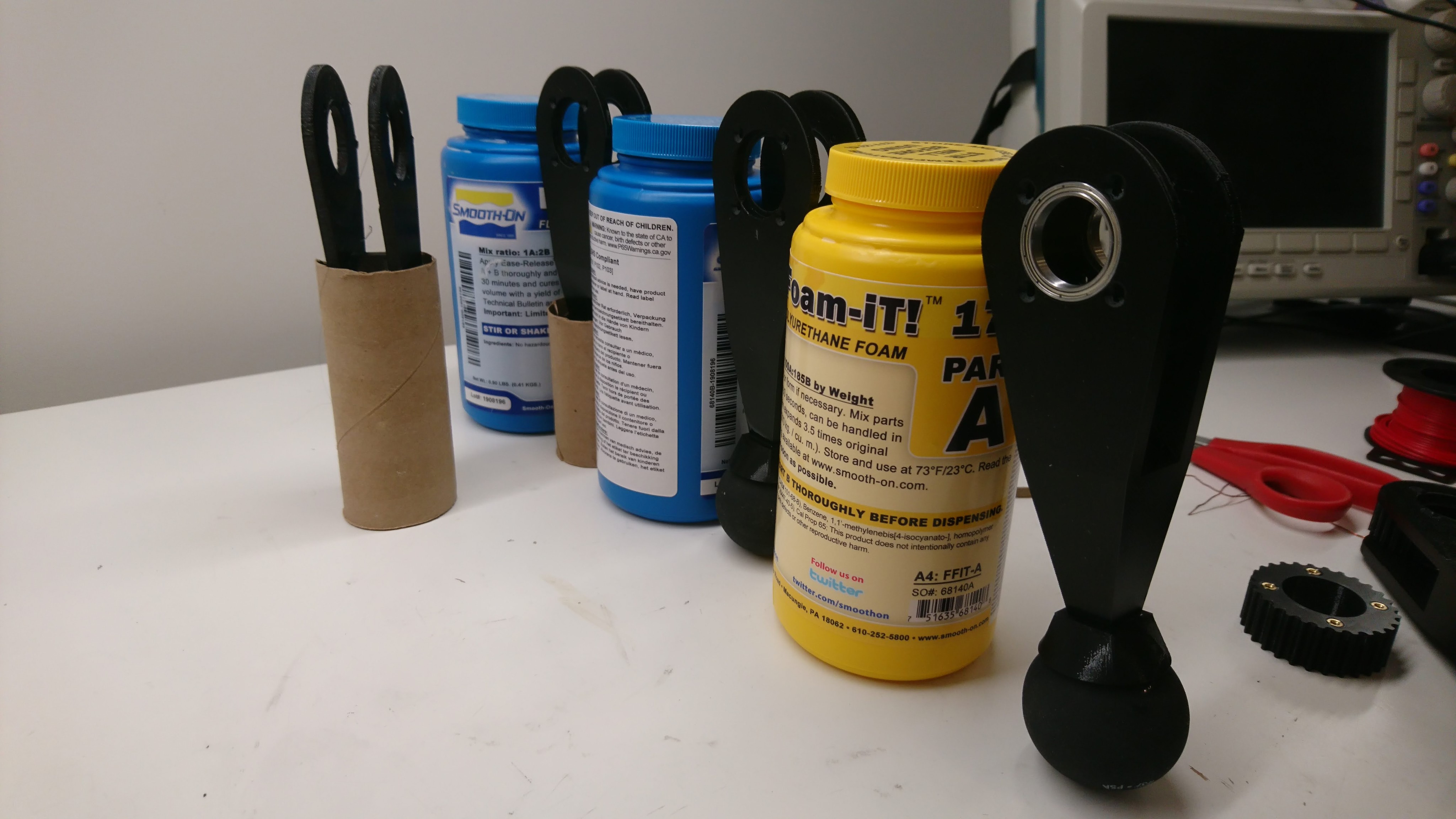
Previously, I described the overall plan for my improved foot. To make that work, I needed to cast a 3d printed part into the squash ball such that it would likely stay attached during operation, be suitable rigid and yet damped, and do so repeatably.
To start with, I used a random single yellow dot squash ball with a hole cut in one side using a pair of side cutters. For the casting foam, I just used Smooth-On Flex Foam-IT 17, which is what Ben Katz originally used at least. Initially I just mixed up a batch, poured it in to a random level, stuck my bracket in and hoped for the best.
As mentioned long ago in my post on failing more gracefully, it was obvious I wanted to strengthen the lower leg and foot mechanism to remove the point of failure observed there. For now, I’m attempting to basically copy the original Mini-Cheetah foot principle, although with more 3d printing and less machining.
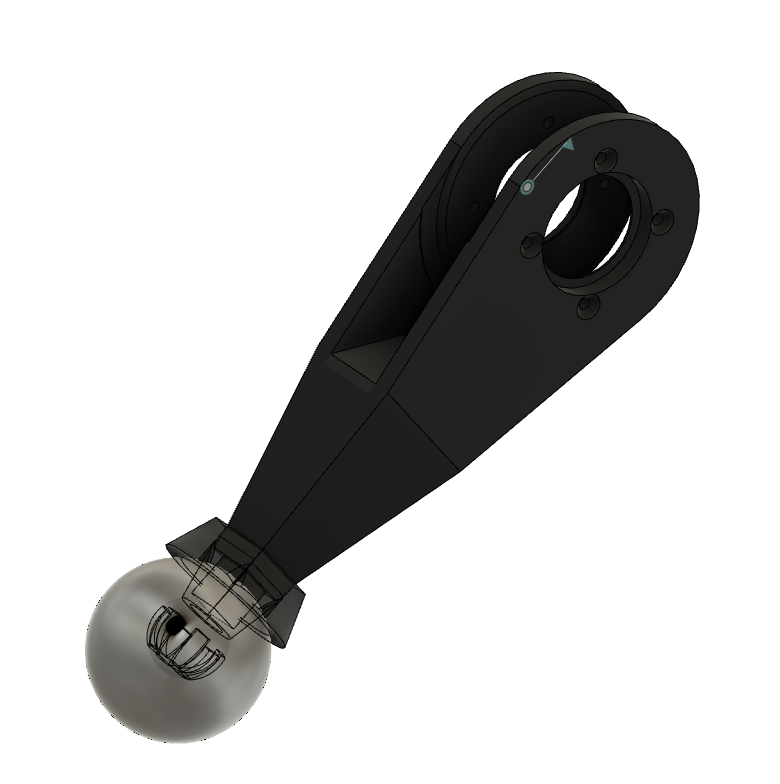
The basic idea is to print the entire lower leg in a single go laying on its side, so that delamination is unlikely. The foot bracket will be cast into a squash ball, then epoxied onto the lower leg.