Archives: Fixture

5 Side PCB Test Fixture

If you look around online, there are lots of examples of PCB test fixtures used to perform end of line testing. In the low to medium volume scale, nearly all of these are either clamshell or 2 side affairs, where probe pogo pins or interfaces are connected to the bottom and top of the board.

When developing the moteus-n1, one of the challenges was the number of right angle board edge connectors it has. Those right angle connectors are what allow it to maintain a very low overall stack height when installed in applications, but are also much harder to perform testing on, since by definition the access points are not vertical. On the base n1, there are 6 total right angle connectors, 2 on each of 3 sides, and future variants may have additional bottom side CAN and power connectors populated to make 8 total right angle connectors.

Resistive heater dummy load

While testing moteus controllers, it is often necessary to experiment with high power conditions. For short durations, any decent sized brushless motor can work, as the windings have a non-zero thermal mass and take a little bit to warm up. However, when testing at high power for extended duration, it can be hard to find a way to get rid of all output energy. Even blowing a fan directly onto a motor only gets you so far when you are trying to get rid of 1kW.

Updated moteus test fixture

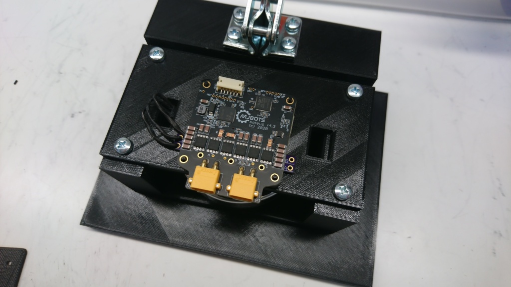
I documented the first test fixture I built for moteus some time ago. As the shipment volumes have gone up, the fixture became something of a limitation, and also was a little problematic in a few ways.

The old “state of the art”

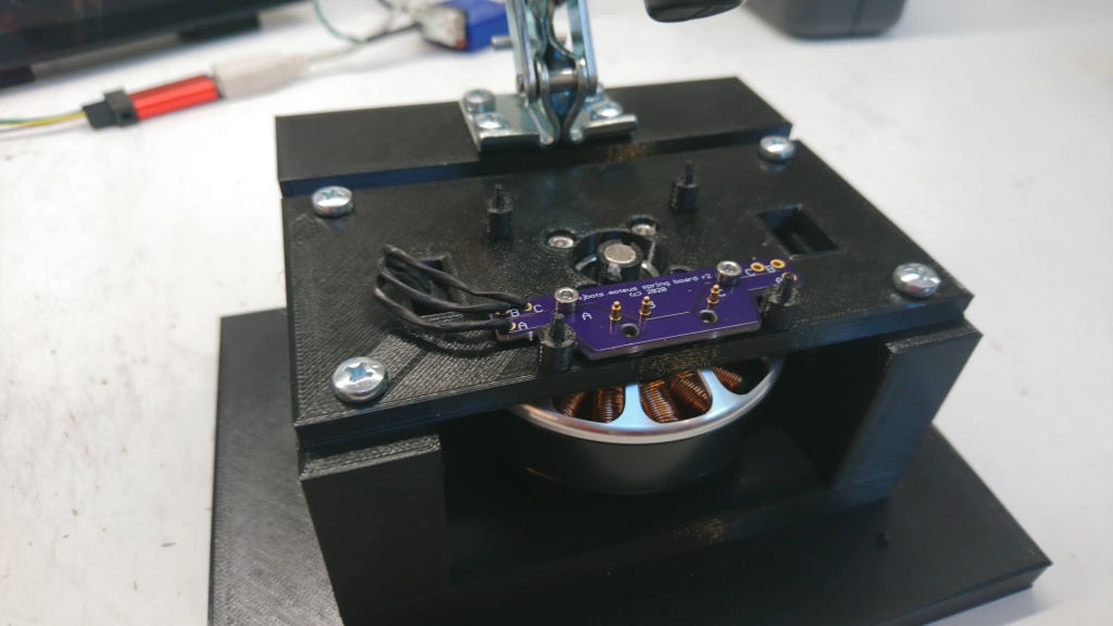
First, it relied on attaching 3 connectors by hand for each test, which was a decent fraction of the cycle time. Second, the pogo pins it used were non-replaceable, and also connected only to the debug phase wire test vias, which were tiny. They wore out relatively quickly, and replacing them required building a whole new board. Finally, since the pogo pins were PCB mounted, a PCB needed to be printed for any change in the pin locations or which pins to probe.

Gear testing fixtures

The qdd100 servo uses a planetary geartrain as the transmission reducer. This consists of an outer ring gear, an inner sun gear connected to the rotor as the input, and 3 planets connected to the output. The tolerances of these gears directly impacts the performance of the servo, namely the backlash and noise.

To date, I’ve been hand-binning these and testing each servo for noise at the end of production. To make that process a bit more deterministic, and with less fallout, I’ve built up a series of manual and semi-automated gear metrology fixtures to measure various properties of the gears.

Quad feet construction fixture

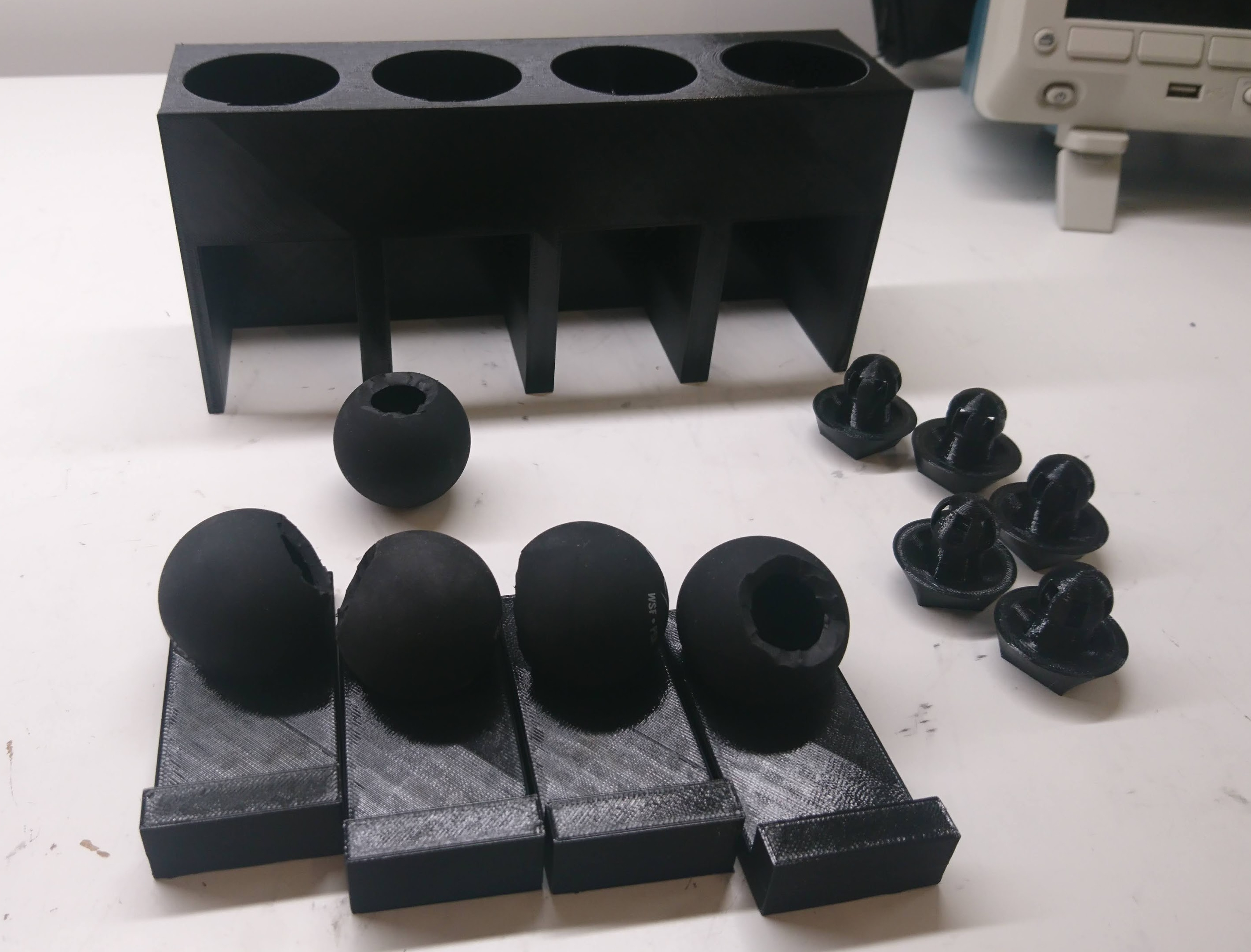
The quad A1 was the first robot I built with foam cast feet.  When I did the first feet, I jury rigged a fixture from some old toilet paper rolls to hold things in place while they were curing.  When I went to rebuild with my most recent leg geometry, I figured it was time to get at least a little more serious.  Thus, my new leg casting fixture:

dsc_0578

When an insert is cast into place, it is set on one of the trays, the tray is inserted into a slot, and then a weight can be placed on top and constrained by the fixture.

Leg zeroing fixture

As part of provisioning a quad A1, or anytime the mechanical configuration has been changed, I need to go and record where the zero position of all the joints is.  The “0” position for the software now is with the shoulders perfectly horizontal, and the upper and lower leg sticking straight down.

Up until now, every time I’ve done this it has just been by eyeballing and with lots of foam and bubble wrap to shim things into place long enough to record the level.  Sometimes I had to go back and try a few times, as even determining when something is straight is not, well, straightforward.

Programming and testing moteus controllers

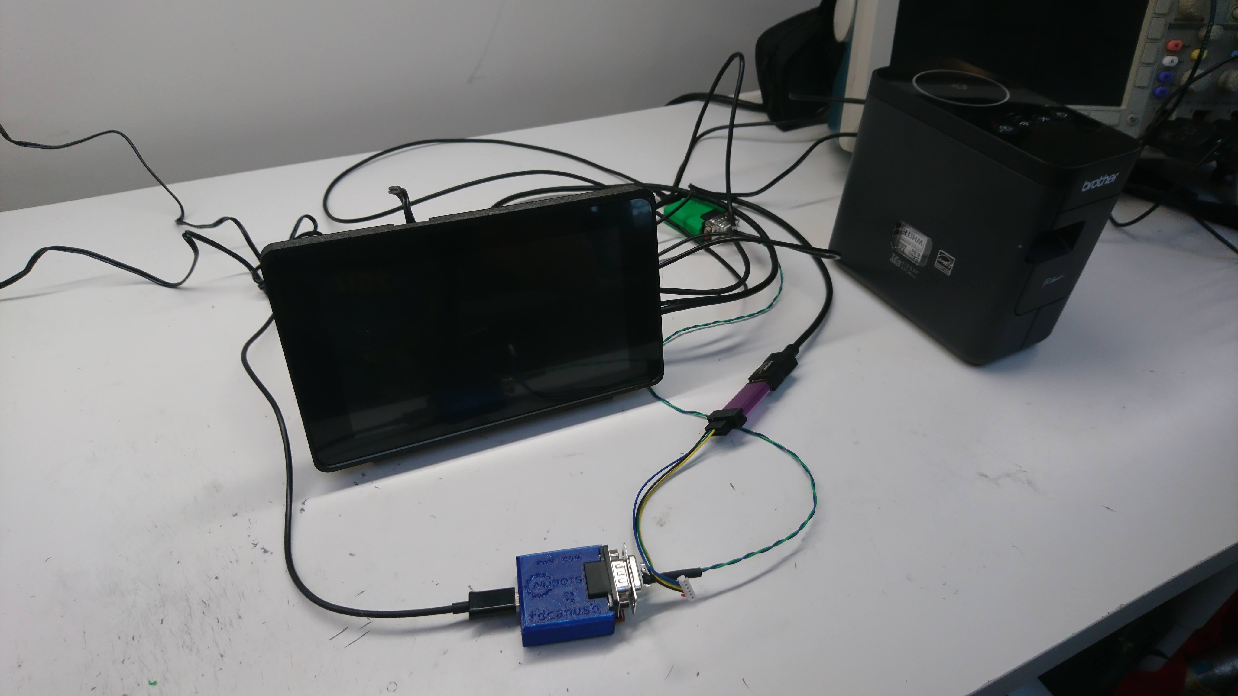
Like with the fdcanusb, I built a programming and test fixture for the moteus controllers.  The basic setup is similar to the fdcanusb.  I have a raspberry pi with a touchscreen connected via USB to a number of peripherals.  In this case, there is a STM32 programmer, a fdcanusb, and a label printer.  Here though, unlike with the fdcanusb fixture, I wanted to be able to test the drive stage of the controllers and the encoders too.

Programming a lot of fdcanusbs

To get ready for the initial limited release of fdcanusbs, I needed to program a whole bunch of them.  Further, I wanted to be able to scale up a few factors of two without being too annoyed with manual steps.  Thus, enter my minimal programming fixure:

dsc_0188

It isn’t much, just a raspberry pi 3b+, the official 7" rpi touch screen, a STM32 programmer, a “fixtured” fdcanusb to drive the device under test, and a label maker.  The touch screen is mostly there to display the results if anything goes awry, as in normal operation there is just one button to push.  The final cycle time to program a fdcanusb and install it into the enclosure is around two minutes, which is good enough for now.