qdd100 telepresence demo
I saw a recent Skyentific video and decided to have a try at it myself, check out the result:
Last time I covered the new software library that I wrote to help use all the features of the pi3hat, in an efficient manner. This time, I’ll cover how I measured the performance of the result, and talk about how it can be integrated into a robotic control system.

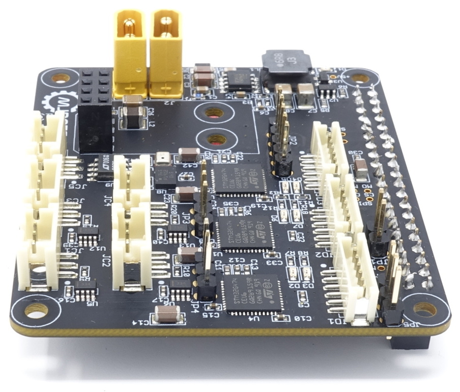
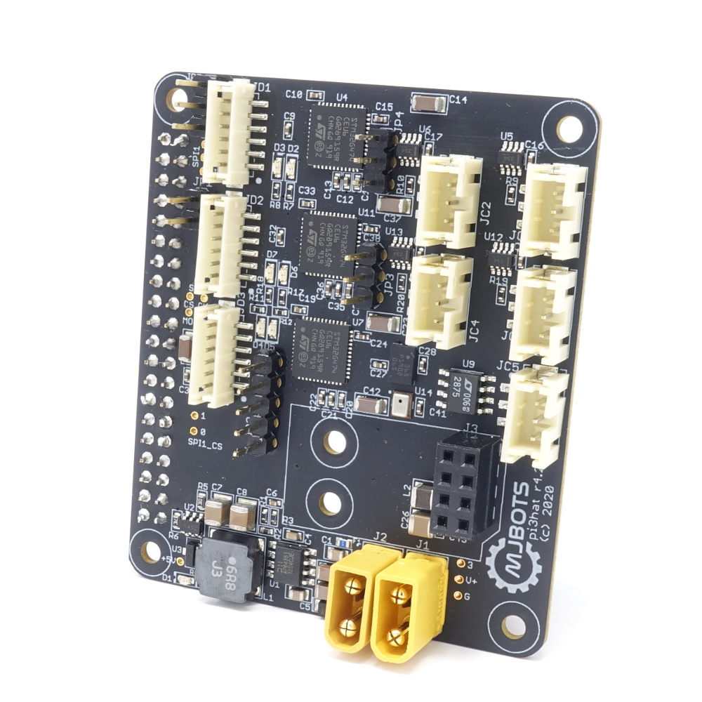
pi3hat r4.2 available at mjbots.com
To check out the timing, I wired up a pi3hat into the quad A1 and used the oscilloscope to probe one of the SPI clocks and CAN bus 1 and 3.
The pi3hat r4.2, now in the mjbots store, has only minor hardware changes from the r4 and r4.1 versions. What has changed in a bigger way is the firmware, and the software that is available to interface with it. The interface software for the previous versions was tightly coupled to the quad A1s overall codebase, that made it basically impossible to use with without significant rework. So, that rework is what I’ve done with the new libpi3hat library:
I’ve now got the last custom board from the quad A1 up in the mjbots store for sale, the mjbots pi3 hat for $129.
This board breaks out 4x 5Mbps CAN-FD ports, 1 low speed CAN port, a 1kHz IMU and a port for a nrf24l01. Despite its name, it works just fine with the Rasbperry Pi 4 in addition to the 3b+ I have tested with mostly to date. I also have a new user-space library for interfacing with it that I will document in some upcoming posts. That library makes it pretty easy to use in a variety of applications.
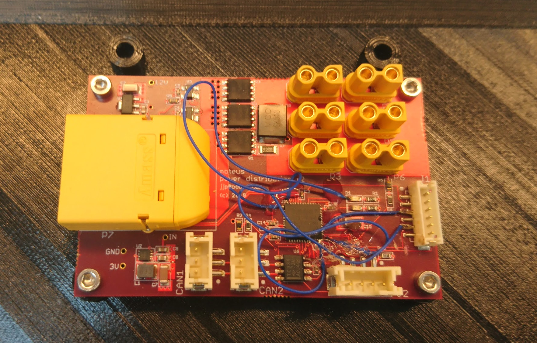
While I was able to make the r2 power distribution board work, it did require quite a bit more than my usual number of blue wires and careful trace cutting.

Thus I spun a new revision r3, basically just to fix all the blue wires so that I could have some spares without having to worry about the robustness of my hot glue. While I was at it, I updated the logo:
After getting the power to work, the next step in bringing up the new quad’s raspberry pi interface board is getting the FDCAN ports to work. As described in my last roadmap, this board has multiple independent FDCAN buses. There are 2 STM32G4’s each with 2 FDCAN buses so that every leg gets a separate bus. There is a 5th auxiliary bus for any other peripherals driven from a third STM32G4. All 3 of the STM32G4’s communicate with the raspberry pi as SPI slaves.
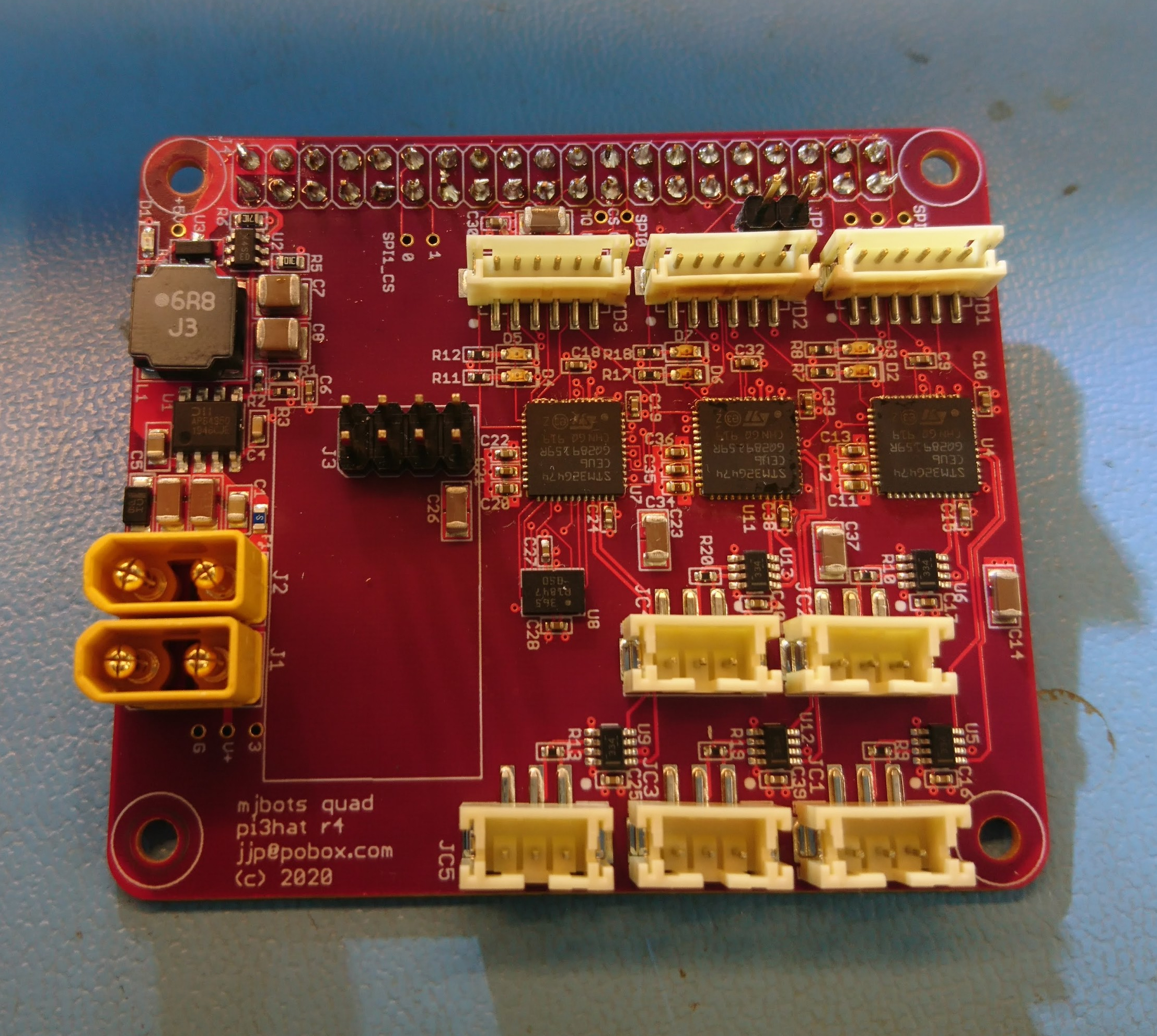
With the new FD-CAN based moteus controllers I need a way for the raspberry pi to communicate with them. Thus I’ve got a new adapter board in house that I’m bringing up:

This one has 5 independent FD-CAN channels, an IMU, a port for an nrf2401l RF transceiver as well as a buck converter to power the computer from the main battery bus.
The prototypes were largely constructed by MacroFab, although I did the Amass connectors and the STM32s because supply chain issues prevented me from getting those parts to MacroFab in time.
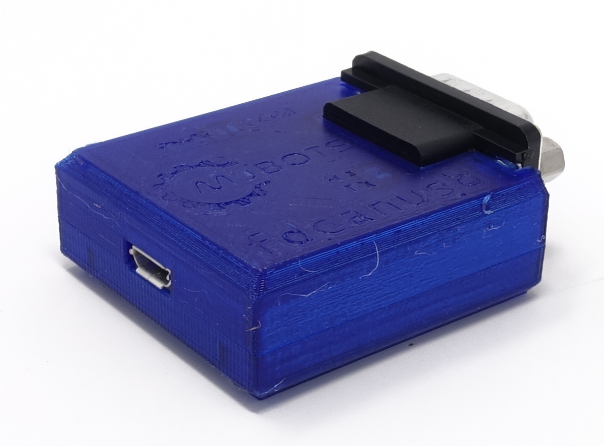
I’ve received my first production run of the fdcanusb CAN-FD USB adapters and they are up for sale at mjbots.com!

While this is necessary for interacting with the moteus controller, it is also a fine general purpose CAN-FD adapter. At the moment, the USB interface is a platform independent line based serial one (Windows, Linux, MacOS). It doesn’t yet interoperate with SocketCAN on linux, but hopefully that will be resolved in the not too distant future.
One final piece of porting that needed to happen for the moteus controller r4.x series was the bootloader. The r3.x series has a bootloader, which allowed re-flashing the device over the normal data link, but that was largely specific to the RS485 and mjlib/multiplex framing format. Thus, while not particularly challenging, I needed to update it for the FD-CAN interface used on the r4.x board.
The update itself was straightforward: https://github.com/mjbots/moteus/compare/406f01…1123a9
For now, on the assumption I will in the not too distant future deprecate the r3.x series, just duplicated the entire bootloader, replacing all the communication bits with FDCAN and stm32g4 appropriate pieces. As before, this bootloader is designed to only operate after the normal firmware has initialized the device, and also is required to be completely standalone. To make code size easier to manage, it makes no calls to any ST HAL library and manipulates everything it needs purely through the register definitions.
I introduced the fdcanusb previously, now I’ll describe some of the process and challenges in getting it to work.
My initial challenges were around the PCB design and manufacturing. To begin with, my very first revision was sent out for manufacturing with the same incorrect pinout as the moteus controller r4.0 and thus was only really usable as a paperweight. Second, the supply of STM32G474 chips seems to be spotty now, so for r2 I had to scavenge chips from the boards that had broken pinouts.