Archives: Build

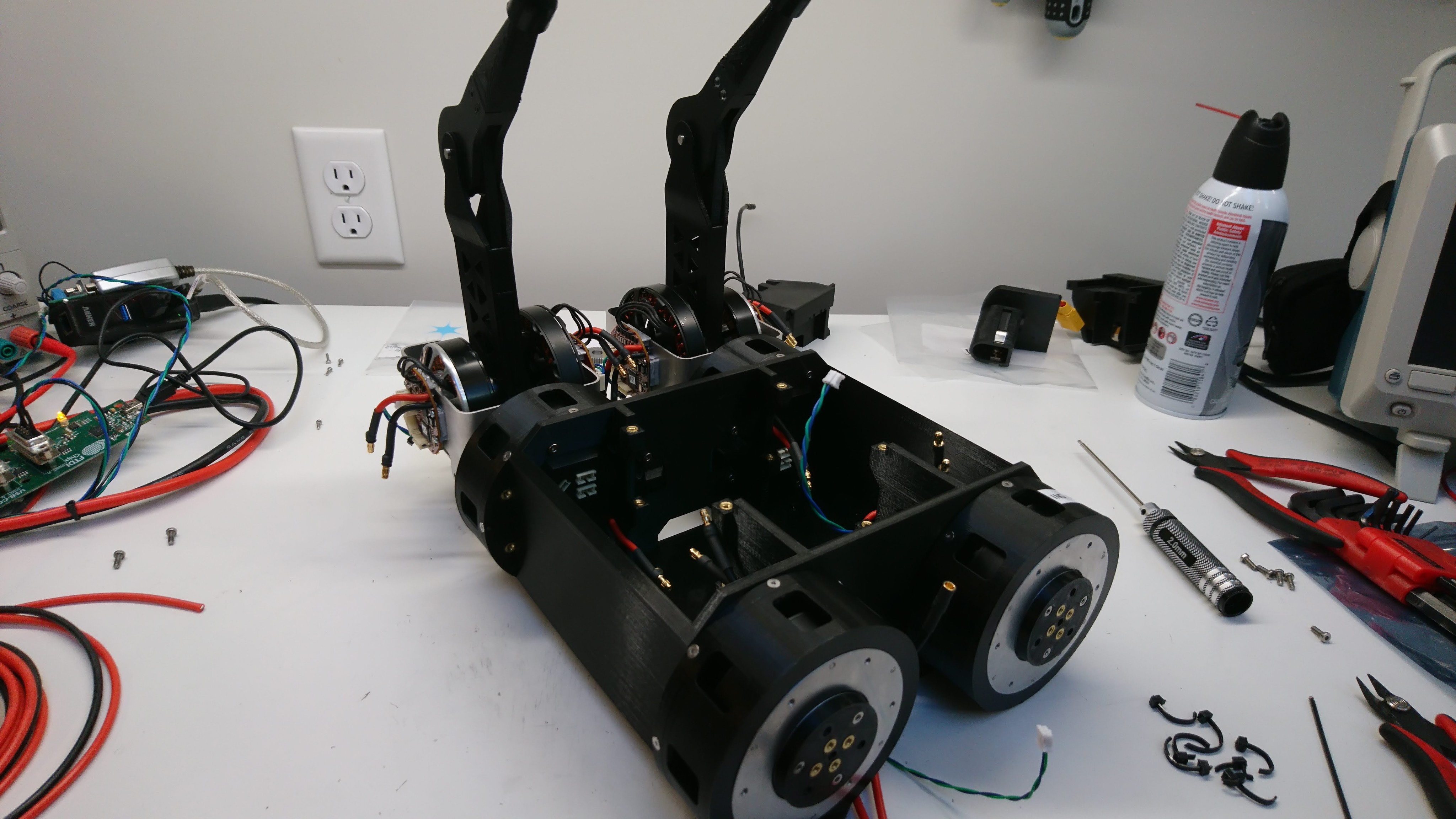
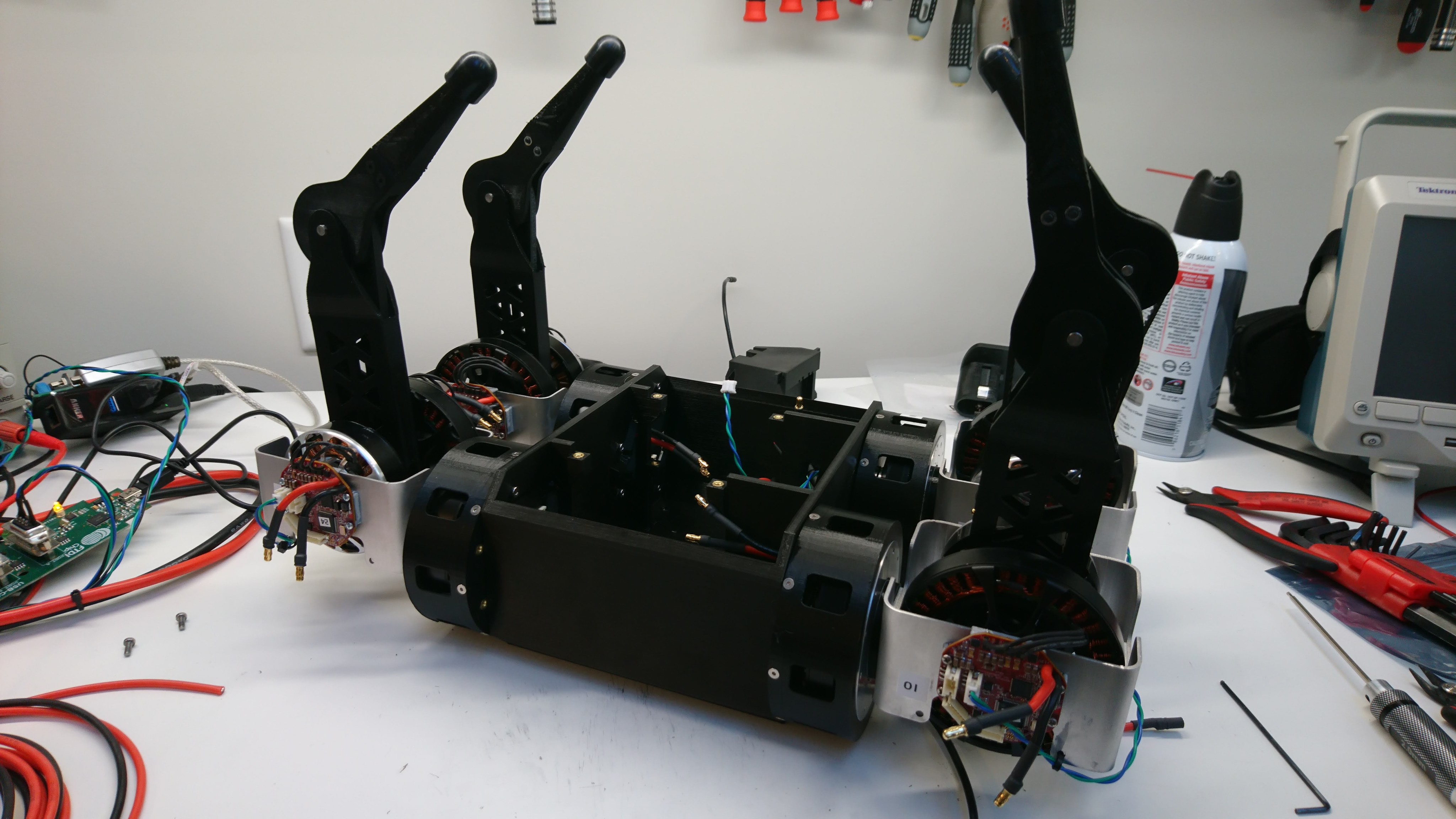
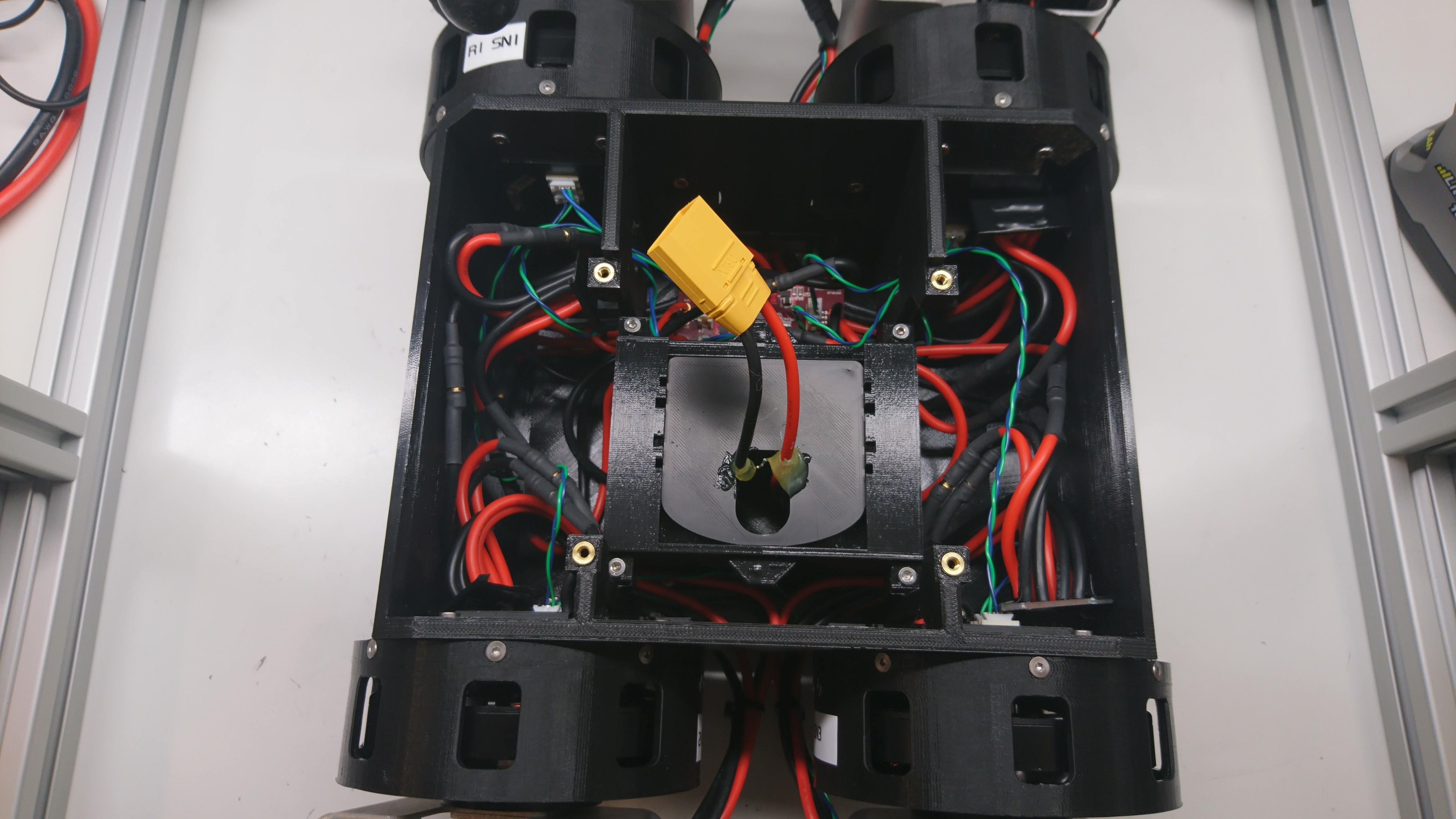
First assembled full rotation leg

As I described earlier, the first draft brushless quadruped leg design was insufficiently robust for the gearbox driven motors and I am updating it to a geometry that allows full rotation.  I’ve made at least some progress on that front, so here is an intermediate report.

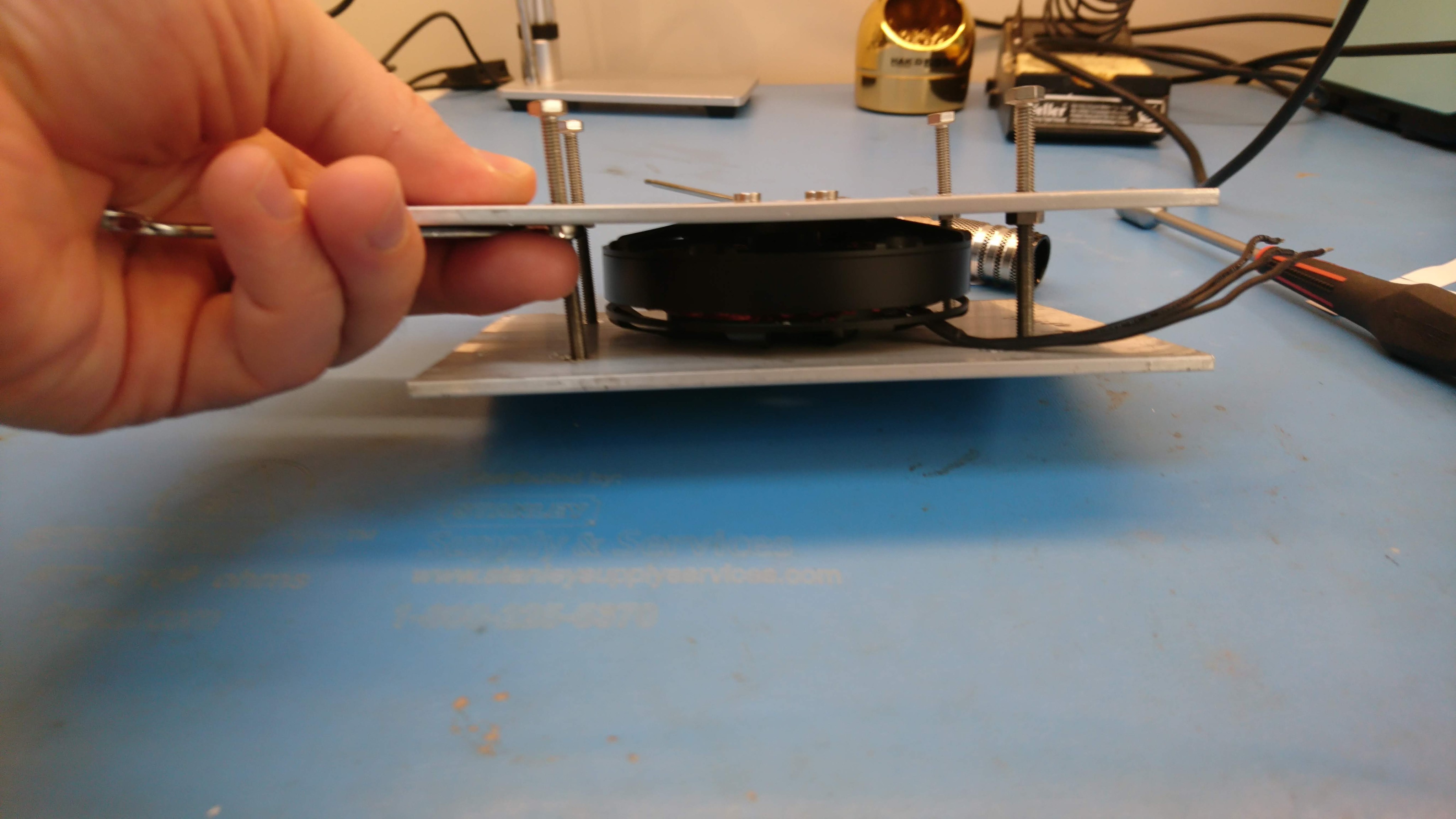
First, after doing some analysis, it appeared that the 3mm pitch 6mm wide belt was unlikely to be able to carry the full torque from the motors.  So I’ve switched to a 5mm pitch 15mm wide belt, which while still unable to carry the full torque indefinitely is only a factor of 2 or 3 off instead of a factor of 20 off.  Secondly, I added a bearing opposite the upper pulley so that it is supported from both sides.  The recommended belt tension for this belt works out to something like 120lb, which is a fair amount of cantilevering, even over the 16mm wide pulley.  The updated CAD looks like:

Walking and Maker Faire!

Alert!  I’m at Maker Faire Bay Area all weekend in the Mech Warfare area in Zone 2 (May 17-19, 2019 for you time travelers from the future).  Drop by and say hi!

If you were left in suspense last time, yes, the robot can walk!  Getting it to do so in a minimal way was relatively painless.  What I found, which hadn’t happened in earlier iterations, is that many types of dynamic motions would cause the lower leg belts to jump a tooth.  Needless to say, this was nearly universally fatal, as there is no direct position sensing of the lower leg.  This robot is heavy enough that my simulacrum 3d-printed timing belt pulleys just don’t cut it.

The gearbox sprint

As mentioned last time, I needed to build a lot of gearboxes and new leg assemblies in a very short amount of time. So, I got to work.

Machining operations

I made a new fixture for holding stators to be extracted:

Stock in the vise

Stock in the vise

Countersinks milled

Countersinks milled

Stator mounted and fractionally machined

Stator mounted and fractionally machined

I turned down 8 more internal gears. To begin with, my mandrel had warped enough from the first gears that I had to add some heat set inserts to hold a cap to keep the gears on. Then on the last 2 gears, I got greedy, went too fast, and my lathe mandrel melted entirely.

Wiring up the gearbox chassis

Now that I had a set of 4 at least minimally working lateral servos, I needed to wire up the chassis so that everything had power and data.  Here are some pictures of that process:

Two legs installed

Two legs installed

Four legs installed

Four legs installed

Joint cable routing

Joint cable routing

Times four

Times four

Suspended from the test fixture

Suspended from the test fixture

Four sets of busbars, the junction board, and a shore power battery simulator

Four sets of busbars, the junction board, and a shore power battery simulator

Lateral servo gearbox build(s)

After completing one gearbox, I needed to build at least 4 more of them to replace the lateral servos on Super Mega Microbot (2).  So, I got to work.  First, I disassembled 5 more BE8108 motors.

dsc_2140

Then, I drilled out the rotors, this time using the mill at AA.

dsc_2145

Next I removed the stators from their backing.  This was painful enough last time, that I tried a new technique using the mill to do most of the work.  Unfortunately, one of the stators was critically damaged during my initial experimentation.  So, now down to 4 survivors.

Rebuild of gearbox assembly

After finally getting the darned thing apart, and printing a new outer housing, I went about re-assembling the whole mechanism.  This time, I tried to take care to make the future disassembly less painful.

To start with, I filed down the problematic outer bearing interfaces of the sun gear holder so that the bearings were a slip fit over them.  These two interfaces don’t need to be particularly snug, so that was easy enough, if monotonous, to accomplish.  I also machined out a some pockets around the magnet hole, to make it possible to just hot-glue the position magnet in place and more easily extract it.

Rotor and stator alignment

Last time I covered getting to the point of having the rotor installed into the gearbox.  Here we’ll look at making it actually work in that configuration.

When I first got the rotor in place, it was clearly not centered properly.  Although much closer than in the plastic gearbox, it did interfere with the stator during a portion of a revolution.  The first obvious problem was that the primary shaft wasn’t making it all the way through the front shaft bearing.  That should have been an easy fix, but for two different very annoying reasons.

CNC machined planet output and front housing

Shortly after receiving the sun gear holders, I received the first iterations of the planet output and front housing.

20x of the planet output

20x of the planet output

20x front housing

20x front housing

Both of these seem to have actually adhered to the tolerances I requested, so thankfully it won’t be too hard to fit everything together.  However, getting everything together for the first time did involve a comedy of errors – a lack of planning for assembly order, a lack of foresight into how things would be *dis-assembled*, a stubbornly stuck shaft, and plenty of broken parts.

Sun gear holder shrink fit

As discussed last time, the sun gear holders I had CNC machined unintentionally had a slightly undersized bore that the sun gear was going to fit into.  The allowance was large enough, that there was no way I was going to press it into place as is.  So, I decided to try a shrink fit, but before I did I wanted to do some math to verify that it was possible with the temperatures I could easily achieve and that I wasn’t going to explode (or even just fracture) the aluminum part from over-stressing it.